Micro-combustor

A burner, micro-miniature technology, used in burners, gas fuel burners, combustion types, etc., can solve the problems of unsustainable catalytic effect of catalysts, increase the complexity of system processing, reduce the compactness of burners, etc., to shorten the ignition time The effect of prolonging time, reducing energy and reducing heat dissipation loss

Inactive Publication Date: 2011-09-14
HUAZHONG UNIV OF SCI & TECH
View PDF5 Cites 19 Cited by
  • Summary
  • Abstract
  • Description
  • Claims
  • Application Information

AI Technical Summary

Problems solved by technology

But the complex three-dimensional structure of this burner makes its machining very difficult
In addition, Zhong Jingjing et al. have proposed a miniature catalytic burner, however, the catalytic effect of the catalyst is not durable
The research team

Method used


Image

  • Micro-combustor
  • Micro-combustor
  • Micro-combustor

Examples


Example Embodiment

[0015] The present invention will be described in more detail below in conjunction with the drawings and embodiments, but the following embodiments are only illustrative, and the protection scope of the present invention is not limited by these embodiments.

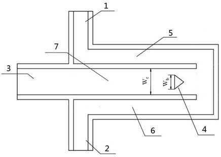
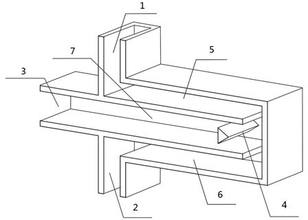
[0016] Such as figure 1 As shown, the micro burner provided by the present invention includes gas inlets 1 and 2, tail gas outlet 3, bluff body 4, preheating channels 5 and 6, and combustion chamber 7. The preheating passages 5 and 6 and the combustion chamber 7 are all flat plates.

[0017] The bluff body 4 is installed at the entrance of the combustion chamber, the cross section of the bluff body is triangular or cylindrical, and its surface can be sprayed with platinum (Pt) and other common catalysts. Width of bluff body 4 W b And the width W of the combustion chamber 7 c The ratio is between 0.3 and 0.6. The preheating channels 5 and 6 are both L-shaped and arranged on the upper and lower sides of the combustion chamber 7,...


PUM


Abstract

The invention discloses a micro-combustor, which comprises a bluff body, two preheating channels and a combustion chamber, wherein the preheating channels and the combustion chamber are all plate-shaped; the cross section of the bluff body is triangular or circular; the bluff body is arranged at an inlet of the combustion chamber; the ratio of the width of the bluff body to the width of the combustion chamber is 0.3-0.6; the two preheating channels are both L-shaped and are respectively arranged at upper and lower sides of the combustion chamber; and outlets of the preheating channels are both communicated with the inlet of the combustion chamber. By using the micro-combustor, the defect of the prior art is overcome. By preheating and catalyzing fuels and air (when a non-pre-mixing combustion mode is adopted) or the pre-mixture of the fuels and air (when a pre-mixing combustion mode is adopted), the energy used for igniting is lowered, the igniting delay time is shortened and the exhaust heat loss is reduced. Besides, a low-speed high-temperature recirculation region formed behind the bluff body is utilized to fully mix the fuels and air, prolong the gas retention time and stabilize the flame. The micro-combustor can be used for efficiently expanding the stable combustion limit and increasing the combustion efficiency and can be widely applied to various micro-power systems.

Description

technical field [0001] The invention belongs to the technical field of gas combustion, in particular to a burner for providing a heat source or a high-temperature gas source for a miniature power device. Background technique [0002] With the rapid development of micromachining technology, various microelectromechanical systems and devices are emerging, such as microsatellites, micropropulsion systems, microrobots, and portable electronic devices such as mobile phones. At present, most of these devices are driven by chemical batteries. However, chemical batteries have disadvantages such as low energy density, large volume and weight, and long charging time. Compared with chemical batteries, hydrogen and hydrocarbon fuels have energy densities that are dozens of times higher. For example, the energy density of a typical liquid hydrocarbon fuel is about 45MJ / kg, while the energy density of the best lithium battery is about 1.2MJ / kg. Therefore, combustion-based micro-miniature...

Claims


Application Information

Patent Timeline
IPC IPC(8): F23D14/26F23D14/46F23D14/66
CPCY02E20/34
Inventor 范爱武刘思远张若昀杨金国刘伟
Owner HUAZHONG UNIV OF SCI & TECH
Why Eureka
Try Eureka