
Ultraviolet LED disinfection effect test device

A disinfection effect test, ultraviolet technology, applied in disinfection, water supply equipment, sanitary equipment for toilets, etc., can solve problems such as lack of testing equipment

Inactive Publication Date: 2014-08-06
SHANGHAI GRANDAR LIGHT ART & TECH
View PDF4 Cites 0 Cited by
  • Summary
  • Abstract
  • Description
  • Claims
  • Application Information

AI Technical Summary

Problems solved by technology

[0005] The technical problem to be solved by the present invention is to provide a UV LED disinfection effect test device in order to overcome the lack of a test device for testing the disinfection effect of LED ultraviolet lamps in the prior art

Method used


Image

  • Ultraviolet LED disinfection effect test device
  • Ultraviolet LED disinfection effect test device
  • Ultraviolet LED disinfection effect test device

Examples


Embodiment 1

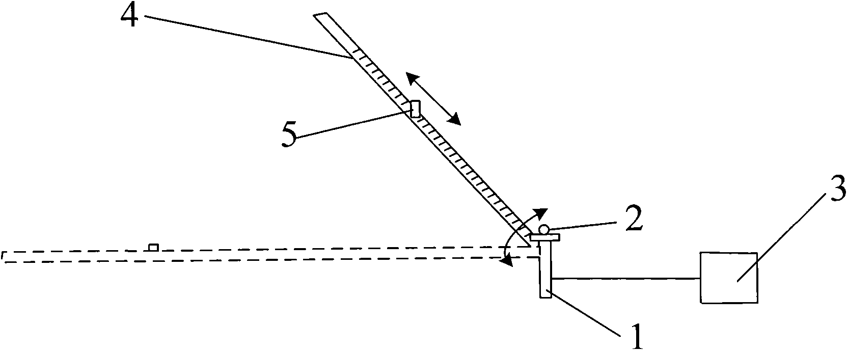
[0030] like image 3 As shown, the ultraviolet LED disinfection effect testing device of the present invention includes a support 1 for placing the LED ultraviolet lamp 2 to be tested, and the support 1 is connected with the LED ultraviolet lamp 2 to be tested by conventional technical means. There is a control system 3 for providing power and controlling the LED ultraviolet lamp 2 to be tested. A cross bar 4 is provided on the support 1, and one end of the cross bar 4 is connected to the support 1 in rotation, and the cross bar 4 can rotate around the support 1 with the support 1 as the center of a circle. When the above-mentioned LED ultraviolet lamp 2 to be tested is installed, The central axis is parallel to the plane of rotation of the crossbar 4 . Preferably, the crossbar 4 is connected to the bracket 1 through an electric motor (not shown in the figure), and the above-mentioned control system 3 drives the electric motor to drive the crossbar 4 to rotate around the brac...

Embodiment 2

[0034] like Figure 5 and 6 As shown, the difference between this embodiment and Embodiment 1 is that the ultraviolet LED disinfection effect test device in this embodiment also includes at least one arc-shaped track 6 with the bracket 1 as the center. The other end of the crossbar 4 is mounted on the arc track 6, so that the crossbar 4 is more stable during rotation. The central angle of the arc track 6 ranges from 0° to 360°, and is not equal to 0°. During use, the central angle of the arc track 6 can be selected according to the type of the tested LED ultraviolet lamp to ensure that the central angle of the sector formed by the arc track is not less than the central angle of the radiation area of ​​the LED ultraviolet lamp. size.

[0035] Preferably, an angle scale is also provided on the arc track, so as to facilitate the determination of the rotation angle of the crossbar.


PUM

PropertyMeasurementUnit
angleaaaaaaaaaa

Abstract

The invention discloses an ultraviolet light-emitting diode (LED) disinfection effect test device. The device comprises a support for accommodating an LED ultraviolet lamp to be tested, at least one cross rod which is arranged on the support and can rotate by taking the support as the centre of a circle, a cuvette for accommodating solution to be disinfected and a control system for providing energy for the LED ultraviolet lamp to be tested, wherein the rotary surface of the cross rod is parallel to the central axis of the LED ultraviolet lamp to be tested; and the cuvette is slidably arranged on the cross rod. In the ultraviolet LED disinfection effect test device, the position of the cuvette in a light path of the LED ultraviolet lamp is determined by utilizing the radial movement of the cuvette and the rotation of the cross rod around the support, so that the original ultraviolet light efficiency horizontal tube design is replaced to test the disinfection effect of the LED to be tested at any position in the optical radiation range of the LED directly; and the obtained data is subjected to mathematical simulation so as to draw a three-dimensional diagram of the disinfection effect of a radiation area of the ultraviolet LED to be tested.

Description

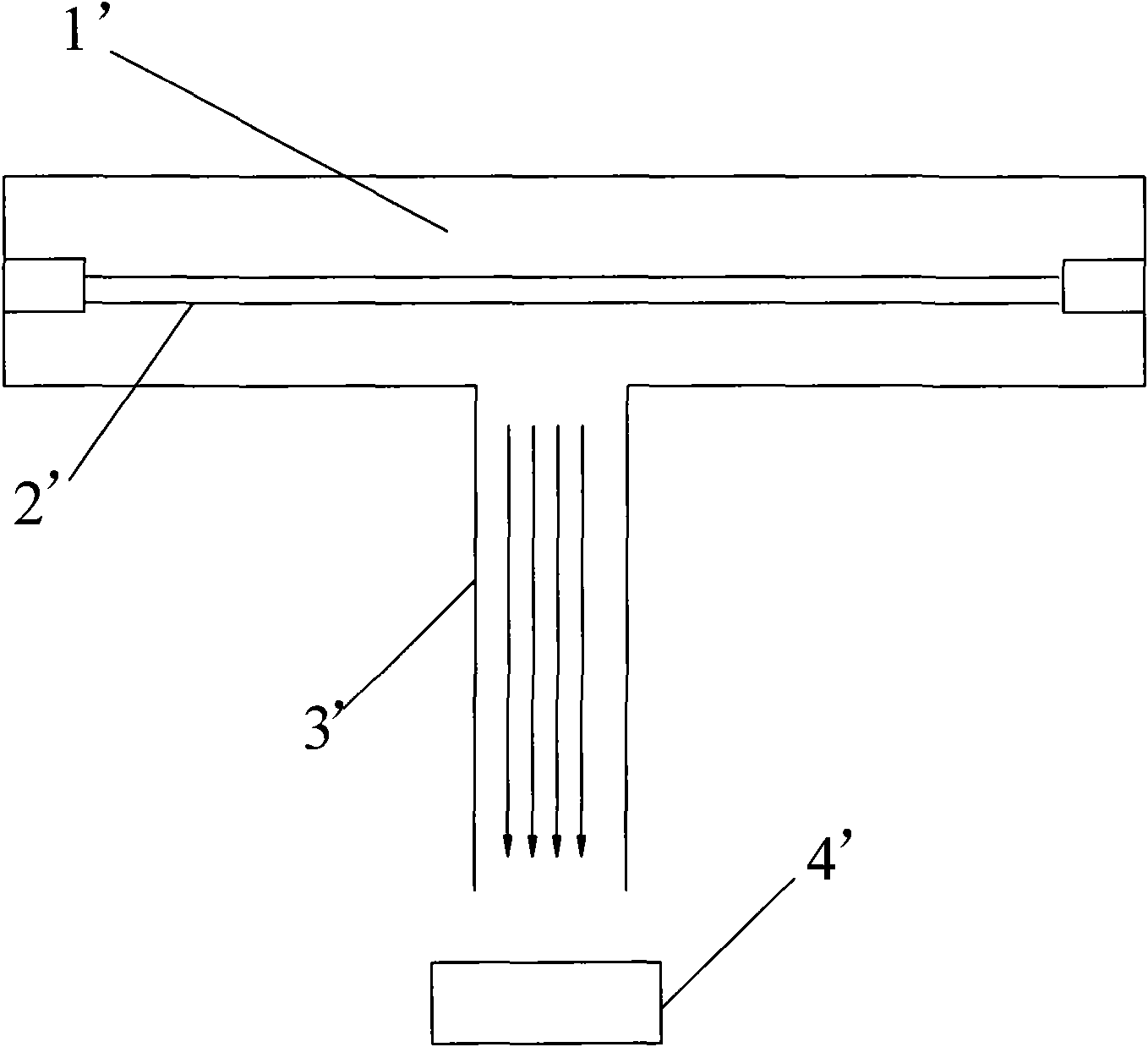
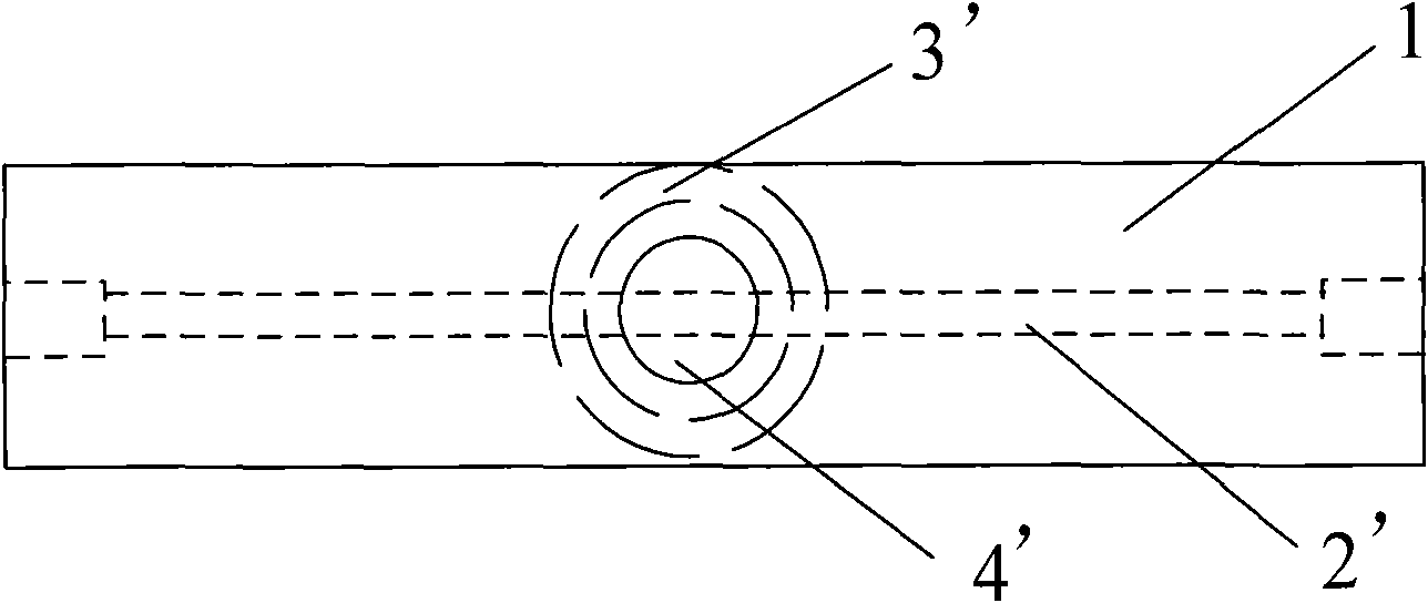
technical field [0001] The invention relates to an ultraviolet LED disinfection effect test device, in particular to an ultraviolet LED disinfection effect test device for detecting the disinfection effect of an LED ultraviolet lamp. Background technique [0002] As a physical disinfection technology that does not produce disinfection by-products, ultraviolet disinfection is quickly accepted by people and put into practical application worldwide. In order to further study the influencing factors of ultraviolet lamp disinfection and determine the specific parameters of project implementation, it is necessary to carry out theoretical research on the disinfection effect of ultraviolet lamps in the laboratory. The existing ultraviolet lamp disinfection effect test system used for theoretical research in a laboratory environment is called a CBD reactor (Collimated Beam Device, CBD). [0003] like figure 1 and 2 As shown, the CBD reactor in the prior art includes a T-shaped cha...

Claims


Application Information

Patent Timeline
Patent Type & Authority Patents(China)
IPC IPC(8): A61L2/28
Inventor 王培李英远祁浩
Owner SHANGHAI GRANDAR LIGHT ART & TECH
Learn More