Film stretching device and method thereof
A stretching device and way-out technology, used in transportation and packaging, thin material handling, flat products, etc., can solve problems such as tearing off, insufficient cooling of the gripping parts, and no cover records covering the gripping parts, etc. The effect of preventing drop in product temperature and suppressing air leakage
- Summary
- Abstract
- Description
- Claims
- Application Information
AI Technical Summary
Problems solved by technology
Method used
Image

Examples
no. 1 Embodiment approach
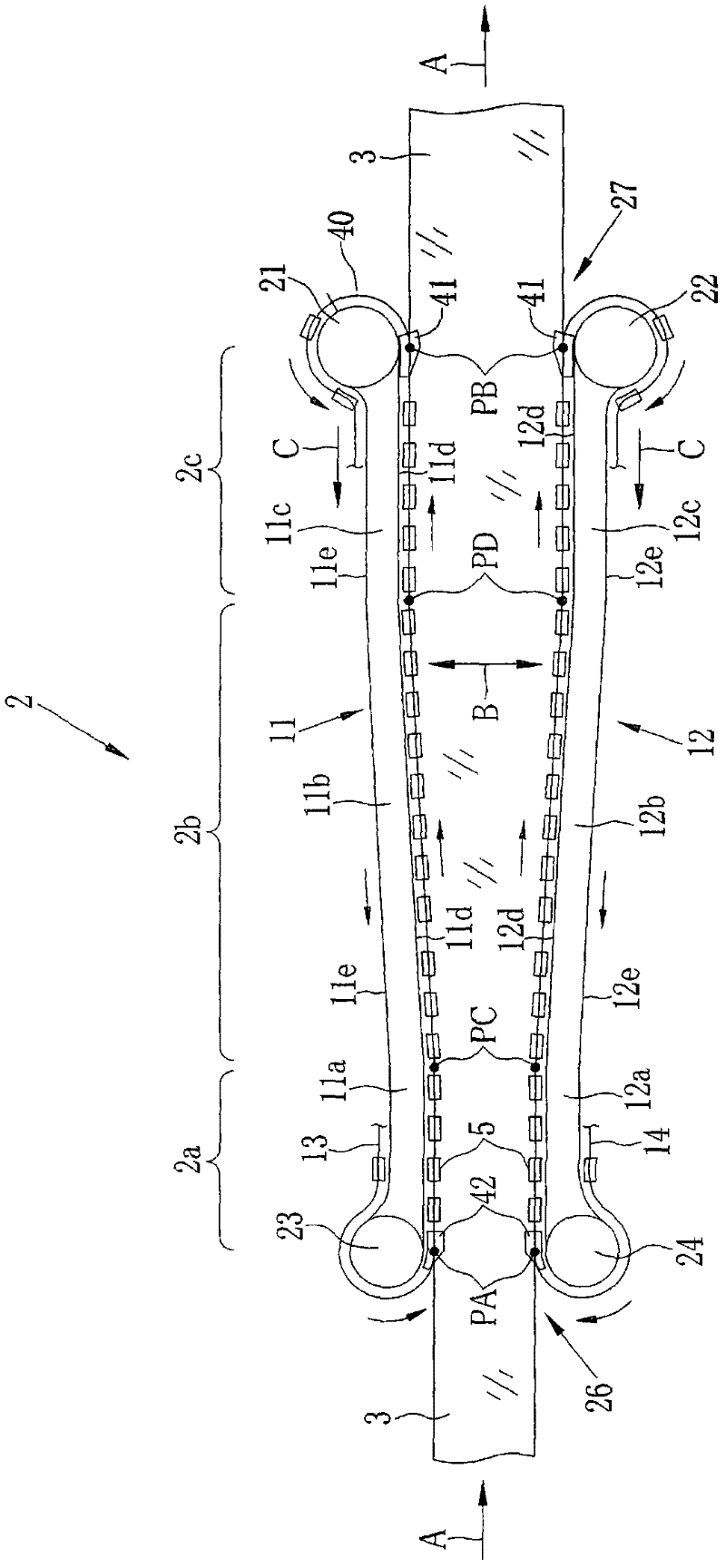
[0048] Such as figure 1 As shown, the clip tenter device 2 stretches the polymer film 3 in the film width direction B while holding both side edges of the polymer film 3 in the film transport direction A with clips 5 , and dries the polymer film 3 .
[0049] The clip tenter device 2 includes a first guide rail 11 , a second guide rail 12 , and first and second chains (circular chains) 13 and 14 . The first and second chains 13 and 14 are guided by the first guide rail 11 and the second guide rail 12 . A plurality of clips 5 are attached to the first and second chains 13 and 14 at a constant pitch.
[0050] Each guide rail 11, 12 is provided with the 1st linear part 11a, 12a, the inclined part 11b, 12b, and the 2nd linear part 11c, 12c. The 1st linear part 11a, 12a extends to film conveyance direction A. As shown in FIG. The inclined parts 11b and 12b are inclined outward with respect to the film conveyance direction A. As shown in FIG. The 2nd linear part 11c, 12c is exten...
Embodiment 1
[0079] exist Figure 7 In the solution film forming apparatus 70 shown, the dope 71 is cast on the surface of a casting belt 82 to form a casting film 85 . The self-supporting cast film 85 is peeled while being supported by the peeling roll 83 to obtain a wet film 88 .
[0080] In the pin tenter device 73 , the wet film 88 with a residual solvent content of 95% by mass was dried to obtain the polymer film 3 after needles were inserted into both ends of the wet film 88 near the inlet and held.
[0081] After the solvent in the film is removed to a predetermined amount in the pin tenter device 73, both ends of the polymer film 3 are cut by the trimming device 93 installed downstream, and the polymer film 3 is sent to a clip tenter. machine device 2.
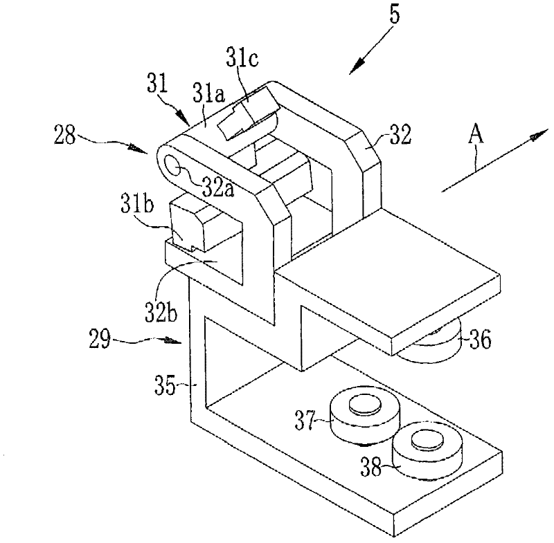
[0082] When the polymer film 3 is conveyed to the grip start position PA in the clip tenter device 2, the head 31c of the gripper 31 of the clip 5 contacts the clip closer 42 and rotates to the grip position, thereby gripping the...
no. 2 Embodiment approach
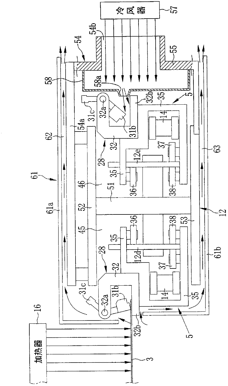
[0097] Figure 13 to Figure 16 In the shown clip tenter device 202 of the second embodiment, a chamber 208 is arranged in the duct 204 . In addition, the same code|symbol is attached|subjected to the same component as 1st Embodiment, and detailed description is abbreviate|omitted.
[0098] Such as Figure 13 to Figure 16 As shown, the outgoing chamber 205 is a space constituted by the center plate 51 of the second guide rail 12 , the top plate 52 , the bottom plate 53 , and the top plate 204 a of the conduit 204 . The circuit chamber 206 is a space constituted by the center plate 51 , the top plate 52 , the bottom plate 53 , and the duct 204 . The outgoing path chamber 205 and the return path chamber 206 are provided so as to be airtight to each other, and the return path chamber 206 is substantially sealed by the conduit 204 . Similarly, an outgoing chamber 205 and a return chamber 206 are also provided on the first guide rail 11 .
[0099] An air cooler 57 for blowing co...
PUM
 Abstract
Description
Claims
Application Information
 - R&D
- Intellectual Property
- Life Sciences
- Materials
- Tech Scout
- Unparalleled Data Quality
- Higher Quality Content
- 60% Fewer Hallucinations
Browse by: Latest US Patents, China's latest patents, Technical Efficacy Thesaurus, Application Domain, Technology Topic, Popular Technical Reports.
© 2025 PatSnap. All rights reserved.Legal|Privacy policy|Modern Slavery Act Transparency Statement|Sitemap|About US| Contact US: help@patsnap.com