Brake control device for elevator

A technology for brake control and elevators, which is applied to brake actuators, transportation and packaging, elevators, etc., and can solve problems such as joint deterioration, passenger discomfort, and high costs.

Inactive Publication Date: 2011-09-21
TOSHIBA ELEVATOR KK
View PDF5 Cites 14 Cited by
  • Summary
  • Abstract
  • Description
  • Claims
  • Application Information

AI Technical Summary

Problems solved by technology

The switch of the elevator is large, so the installation area is large
In addition, the contacts of mechanical switches will deteriorate over a long period of time, so frequent conservative inspections and replacements are required to maintain performance, and the resulting costs are high.
[0011] In

Method used


Image

  • Brake control device for elevator
  • Brake control device for elevator
  • Brake control device for elevator

Examples


no. 1 approach

[0039] First, a first embodiment of the present invention will be described.

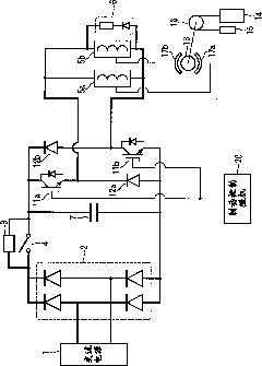
[0040] figure 1 It is a figure which shows the example of the circuit structure of the brake control apparatus of the elevator which concerns on one Embodiment of this invention.

[0041] exist figure 1 In the shown brake control device, the AC power supplied from the AC power supply 1 is full-wave rectified into DC power by the rectifier circuit 2 , and the pulsation of the DC power is smoothed by the smoothing capacitor 7 .

[0042] Such as figure 1As shown, the brake control device is provided with a brake control microcomputer 20 that is a brake control unit that applies predetermined voltages to various elements or opens and closes various switches.

[0043] In addition, a parallel circuit of a limiting resistor 3 and a DC switch 4 is provided between a high potential point on the output side of the rectifier circuit 2 and a high potential point of the smoothing capacitor 7 . This circui...

no. 2 approach

[0063] Next, a second embodiment of the present invention will be described. In addition, the structures of the brake control devices of the following embodiments are the same as figure 1 The ones shown are basically the same, and therefore descriptions of the same parts are omitted.

[0064] Figure 4 It is a figure which shows the example of the circuit structure of the brake control apparatus of the elevator in the 2nd Embodiment of this invention.

[0065] Such as Figure 4 As shown, in the second embodiment of the present invention, compared with the first embodiment, a voltage detector 23a for detecting the voltage across the diode 12a is further provided. Moreover, the voltage detector 23b which detects the voltage of both ends of the diode 12b is provided further. In addition, an AC switch 24 for disconnecting the AC power supply 1 is provided.

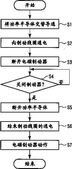
[0066] Figure 5 It is a flowchart showing an example of the operation of the braking control device of the elevator ...

no. 3 approach

[0075] Next, a third embodiment of the present invention will be described.

[0076] Figure 6 It is a figure which shows the example of the circuit structure of the brake control apparatus of the elevator in the 3rd Embodiment of this invention.

[0077] Such as Figure 6As shown, in the third embodiment of the present invention, compared with the second embodiment, a current detector for detecting the current supplied to the brake coils 5a, 5b is provided between the brake coil 5a and the switching element 11b. 25.

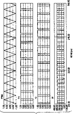
[0078] The brake control microcomputer 20 is different from the operations described in the first and second embodiments. In the PWM control, the switching elements 11a and 11b are controlled to be on and off so that when the current detector 25 detects There is no deviation between the value and the target value, which is the current supplied to the brake coils 5a, 5b in PWM control.

[0079] Generally, the voltage value based on the AC power supply 1 fluct...


PUM


Abstract

The present invention provides a brake control device for an elevator, which is provided with a brake control part (20) that energizes a first brake coil and a second brake coil (5a,5b) for performing energization and cutoff control for semiconductor switches (11a,11b) so one part of a period of energizing the first brake coil is overlapped with one part of a period of energizing the second brake coil. After energization and cutoff is started, motion start of each brake sheet (17a,17b) is determined according to the detection result which is detected by a current detector (25). Along with the determination, the energization and shutoff control is performed for the semiconductor switch so the current value of each brake coil is smaller than that in determination.

Description

technical field [0001] The present invention relates to an elevator brake control device that controls a brake device that performs a braking operation of a braked body such as a hoist. Background technique [0002] Figure 16 It is a figure which shows the structural example of the circuit of the brake control apparatus of a conventional elevator. Figure 17A , Figure 17B , Figure 17C It is a figure which shows an example of the output waveform of the brake control apparatus of a conventional elevator. [0003] The electromagnetic braking device of the elevator (for example, refer to Patent Document 1 and Patent Document 2) such as Figure 16 As shown, it includes a series circuit of a DC power supply 41, a mechanical first switch (S1) 44, and a brake coil 45. The electromagnetic brake device uses brake pads to mechanically brake a braked body such as a hoist. . A series circuit of a DC power supply 42 and a mechanical second switch ( S2 ) 43 is connected in parallel ...

Claims


Application Information

Patent Timeline
IPC IPC(8): B66B1/32F16D65/18
Inventor 大坪亮
Owner TOSHIBA ELEVATOR KK
Why Eureka
Try Eureka