Device and method for in situ measurement of energy distribution of focused laser faculae

A technology of laser spot and energy distribution, which can be applied to measurement devices, optical devices, and electrical radiation detectors for photometry. It can solve problems such as inability to measure and large errors, and achieve the effect of overcoming weaknesses.

Inactive Publication Date: 2011-09-21
THE NAT CENT FOR NANOSCI & TECH NCNST OF CHINA
View PDF5 Cites 10 Cited by
  • Summary
  • Abstract
  • Description
  • Claims
  • Application Information

AI Technical Summary

Problems solved by technology

For the focused laser spot, this method will introduce a large error, and even cannot measure

Method used


Image

  • Device and method for in situ measurement of energy distribution of focused laser faculae
  • Device and method for in situ measurement of energy distribution of focused laser faculae
  • Device and method for in situ measurement of energy distribution of focused laser faculae

Examples


Embodiment 1

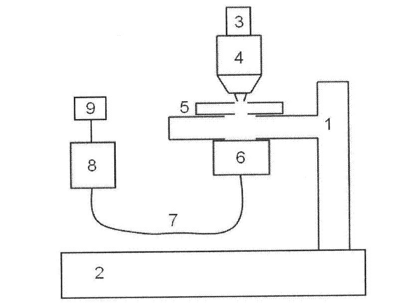
[0033] See attached figure 1 , make a laser spot energy distribution measuring device.

[0034] The small hole part of the present embodiment is made by the following steps,

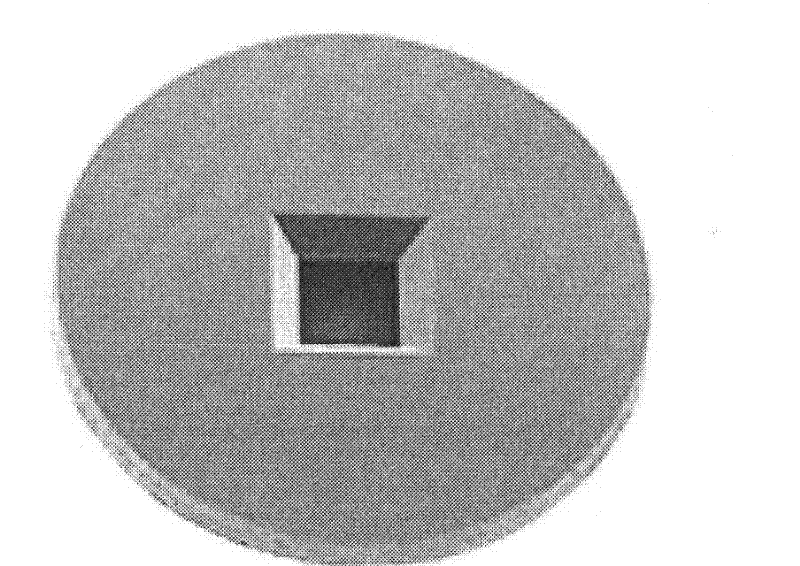
[0035] (1) Select a silicon wafer with a silicon nitride film window purchased on the market (see attached figure 2 ), the thickness of the silicon nitride film window is 200 nanometers; the shape of the window can be circular, rectangular or square;

[0036] (2) Evaporate a layer of gold film on the surface of the sample, and the thickness of the film can be implemented between 500-800 nanometers, as long as the silicon nitride film is opaque;

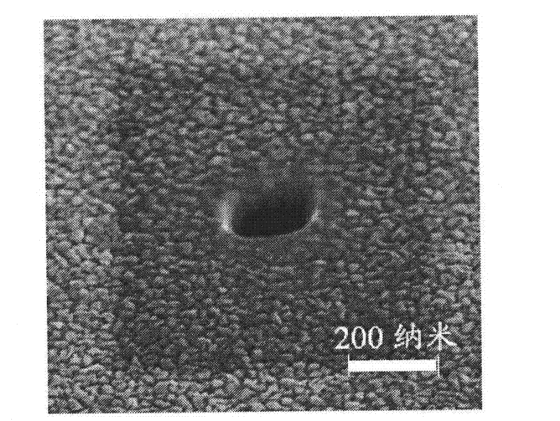
[0037] (3) Utilize focused ion beam technology to etch the required circular through hole (small hole) on the silicon nitride thin film of gold-plated film, the diameter of this circular through hole, for example all can be between 200-300 nanometers, carve through Gold-plated film and silicon nitride film (see attached image 3 and Figure 5 ).

[0038] ...

Embodiment 2

[0049] Follow the method and steps similar to those in Example 1.

[0050] See attached figure 1 , make a laser spot energy distribution measuring device.

[0051] The small hole part of this embodiment is made by the following steps:

[0052] (1) adopt the silicon wafer that has silicon nitride film groove (window) purchased on the market, wherein, the thickness of silicon nitride film groove is 200 nanometers;

[0053] (2) vapor-deposit a layer of gold film on the surface of the silicon wafer with the silicon nitride film groove (window), the thickness of the gold film is 500-800 nanometers, to ensure that the silicon nitride film is opaque; the groove is square;

[0054] (3) Etching a circular through hole with a diameter of 200-300 nanometers on the gold-plated silicon nitride film by using focused ion beam technology. The through hole is used to transmit a small amount of laser signal to prevent oversaturation of the detector; the diameter of the through hole directly...


PUM


Abstract

The invention relates to a device and method for in situ measurement of energy distribution of focused laser faculae. The device is fixed on a high-precision translation stage by a bracket, wherein a bore for fixing a bore part is formed on a desktop of the bracket; a lens of a microscope is vertical to the bore part; a collecting lens is arranged under the bore of the desktop; the collecting lens is connected to a detector through an optical fiber; the detector is used for acquiring a transmitted laser signal and inputting the laser signal to a data processor; and an energy distribution chart of the laser faculae is acquired after the measured data are processed by the data processor. The measuring method comprises the following steps: confirming the bore position by utilizing the microscope and focusing the lasers to the bore position; adjusting and setting an exposure time of the detector; scanning and exposing according to a set step width; and supplying the energy distribution chart of the laser faculae by the data processor. According to the device and method, the accurate measurement for the energy distribution of the focused laser faculae is realized by utilizing the bore part to scan the laser faculae and coupling the acquired laser signal to the high-sensitivity detector with a wide dynamic response scope.

Description

technical field [0001] The invention relates to an optical measurement device and method, in particular to a device and method for measuring the energy distribution of focused laser spots. Background technique [0002] Laser has a wide range of applications in industry, medicine, military and other fields. Similarly, in the field of scientific research, lasers also play a very important role. Laser and microscope coupling devices such as laser micro-Raman spectrometers, laser confocal microscopes, two-photon fluorescence microscopes, and optical tweezers are all based on lasers. up. In specific experimental research, the shape and energy distribution of the laser spot focused by the microscope lens can provide a lot of useful information, which is of great significance in both theoretical and applied research. However, how to realize the in-situ measurement of the energy distribution of the focused laser spot is still a problem. At present, it is difficult for the laser b...

Claims


Application Information

Patent Timeline
Patent Type & Authority Applications(China)
IPC IPC(8): G01B11/00G01B11/08G01B11/24G01J1/42
Inventor 刘新风闫永丽宁廷银裘晓辉
Owner THE NAT CENT FOR NANOSCI & TECH NCNST OF CHINA
Why Eureka
Try Eureka