Self-capacitance change measuring circuit with quick response

A measurement circuit, fast response technology, applied in the direction of measuring electrical variables, measuring resistance/reactance/impedance, liquid level indicators for physical variable measurement, etc. problems, to achieve the effect of reducing system waiting time, short change time and strong anti-interference ability

Active Publication Date: 2011-09-21
上海海栎创科技股份有限公司
View PDF7 Cites 32 Cited by
  • Summary
  • Abstract
  • Description
  • Claims
  • Application Information

AI Technical Summary

Problems solved by technology

[0004] Its disadvantages are: 1) The input signal of the voltage analog-to-digital converter changes from zero, and it takes a long time to stabilize, thus affecting the time required for each detection; 2) The filter capac

Method used


Image

  • Self-capacitance change measuring circuit with quick response
  • Self-capacitance change measuring circuit with quick response
  • Self-capacitance change measuring circuit with quick response

Examples


Embodiment Construction

[0014] The present invention will be further described below with reference to the embodiments shown in the accompanying drawings.

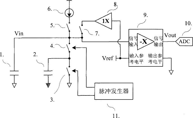
[0015] figure 1 It is the basic system circuit diagram of the measurement circuit. A measurement cycle of this measurement circuit can be divided into three steps, which are:

[0016] 1) Filter capacitor capacitor precharge stage

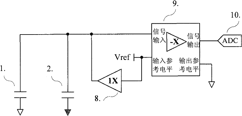
[0017] exist figure 1 In the process, switch (5) and switch (3) are opened, switch (4) and switch (7) are closed, and the filter capacitor and the measured capacitor are quickly charged by the voltage buffer to the level of the reference voltage Vref. Its equivalent circuit is as image 3 As shown, the voltage waveform changes of the signal input and output terminals of the inverting switched capacitor amplifier are as follows Figure 5 t0~t1 stage shown in . The output value of the inverting switched capacitor amplifier is not of concern at this time.

[0018] 2) The filter capacitor is continuously charged and...


PUM


Abstract

The invention relates to a method for quickly detecting capacitance change, which comprises the following steps of: utilizing a detecting circuit to quickly charge a detected capacitor (2) and a filter capacitor (1) at the beginning, thereby establishing a capacitor initial voltage based on a reference voltage Vref; utilizing a current source (6) to charge the filter capacitor (1) while utilizing a switch capacitance circuit to discharge, wherein the switch capacitance circuit is formed by the detected capacitor (2), a switch (3) and a switch (4); after the voltage on the filter capacitor (1) reaches a stable value after a period of time, utilizing a phase-reversal switch capacitance amplifier (9) to amplify a difference value between the voltage of the filter capacitor (1) and the reference voltage Vref; and utilizing an analog-to-digital converter (10) to acquire an output voltage value of the amplifier. When the detected capacitor (1) changes, the voltage on the filter capacitor (1) also changes, and the results acquired by the ADC (analog-to-digital converter) are different. By analyzing the result change of the ADC, the instant relative change of the detected capacitor (1) can be acquired.

Description

technical field [0001] The present invention relates to a self-capacitance change measuring circuit with fast response and an implementation method in an integrated circuit. The method can be used in touch control applications, such as touch keys, capacitive touch screens, mouse touch pads and other wide-ranging applications. Background technique [0002] The basic principle of traditional capacitive touch-sensitive keys is a relaxation oscillator that is constantly charged and discharged. If there is no touch, the relaxation oscillator has a fixed charge-discharge cycle and the frequency can be measured. If the button area is touched with a finger or other object, the dielectric constant of the distributed capacitance of the button will increase, the charging and discharging cycle will become longer, and the frequency will decrease accordingly. By measuring the change in period, the touch action can be detected. [0003] The prior art method has no voltage buffer amplifi...

Claims


Application Information

Patent Timeline
IPC IPC(8): G01R27/26G06F3/044G01F23/26
Inventor 贾朝辉
Owner 上海海栎创科技股份有限公司
Why Eureka
Try Eureka