Optical element, window material, fitting, and insolation shielding device
A technology of optical components and optical layers, which is applied in the field of house partition components and sunlight shading devices, optical components, and window materials, and can solve problems such as lawns that cannot grow
Active Publication Date: 2011-09-21
DEXERIALS CORP
View PDF5 Cites 6 Cited by
- Summary
- Abstract
- Description
- Claims
- Application Information
AI Technical Summary
Problems solved by technology
Therefore, around a building in which the above-mentioned reflective layer is attached to all windows, various problems occur, namely, for example, since a local increase in temperature occurs, a heat island phenomenon occurs in an urban area, and the lawn is only in the Cannot grow in areas illuminated by reflected light
Method used
View moreImage
Smart ImageViewing Examples

Examples
no. 4 approach
[0164] 4. Fourth Embodiment (Example of Providing an Optical Film Containing a Light Scattering Material)
[0165] 5. Fifth Embodiment (example of exposing reflective layer)
no. 6 approach
[0166] 6. The sixth embodiment (an example of setting a self-cleaning effect layer)
no. 7 approach
[0167] 7. The seventh embodiment (an example in which an optical film is applied to a shading device)
Login to View More PUM
| Property | Measurement | Unit |
|---|---|---|
| Storage modulus | aaaaa | aaaaa |
| Storage modulus | aaaaa | aaaaa |
| Thickness | aaaaa | aaaaa |
Abstract
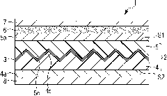
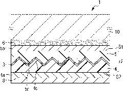
The invention provides an optical element, a window material, a fitting, and an insolation shielding device. The optical element has a first optical layer; a reflective layer; and a second optical layer. The reflective layer includes at least five layers of high refractive-index layers and metal layers alternately laminated. When a thickness L of the entire reflective layer is 80 nm, a ratio [alpha] of an optical thickness of the entire metal layers to that of the entire high refractive-index layers and a ratio [beta] of an optical thickness of a third high refractive-index layer to that of a first high refractive-index layer are included in a first region, when the thickness L is 90 nm, the ratios [alpha] and [beta] are included in a second region, and when the thickness L is 80 to 90 nm, the ratios [alpha] and [beta] are included in a space enclosed by the first region, the second region, and straight lines derived from these regions.
Description
technical field [0001] The present invention relates to an optical element, a window material, a housing fitting, and a solar shading device, each of which can suppress a change in color tone. Background technique [0002] In recent years, architectural glazing of skyscrapers or high-rise houses and window panes of vehicles have increasingly been provided with layers which absorb or reflect some of the sunlight. The above-mentioned glass is used as an energy-saving measure aimed at preventing global warming, and is intended to reduce the load on the air-conditioning system by increasing the indoor temperature when light energy emitted from the sun enters the indoor space through the window. Light energy emitted from sunlight mainly includes light in the visible region with a wavelength ranging from 380 nm to 780 nm and light in the near-infrared region having a wavelength ranging from 780 nm to 2100 nm. In particular, the transmittance of a window in the wavelength range of...
Claims
Login to View More Application Information
Patent Timeline
 IPC IPC(8): G02B5/26E06B9/24E04C2/54E04F10/00B32B15/04G02B5/28
CPCC03C17/36C03C17/366B32B17/10C03C17/3602C03C17/3639C03C17/3649G02B5/208C03C17/3681G02B5/0242G02B5/124G02B5/285G02B5/282G02B5/045C03C17/3613G02B5/0278Y10T428/24967
Inventor 铃木真树榎本正吉田宽则长浜勉谷田部透影山正光
Owner DEXERIALS CORP
Features
- R&D
- Intellectual Property
- Life Sciences
- Materials
- Tech Scout
- Unparalleled Data Quality
- Higher Quality Content
- 60% Fewer Hallucinations
Learn More Browse by: Latest US Patents, China's latest patents, Technical Efficacy Thesaurus, Application Domain, Technology Topic, Popular Technical Reports.
© 2025 PatSnap. All rights reserved.Legal|Privacy policy|Modern Slavery Act Transparency Statement|Sitemap|About US| Contact US: help@patsnap.com