
Coiling base applicable to transformer structure

A winding base and transformer technology, which is applied in the direction of inductance/transformer/magnet manufacturing, coil manufacturing, electrical components, etc., can solve problems such as poor insulation, insulating paint abrasion, and loosening of lead pins, so as to prevent friction and prevent The effect of soldering together

Inactive Publication Date: 2011-09-21
DELTA ELECTRONICS INC
View PDF2 Cites 6 Cited by
  • Summary
  • Abstract
  • Description
  • Claims
  • Application Information

AI Technical Summary

Problems solved by technology

[0008] The main purpose of the present invention is to provide a winding base suitable for a transformer structure, so as to solve the problem that when the known transformer structure is plugged on the system circuit board, the L-shaped lead pins will be loosened due to the assembly process, and the welding When the outlet ends of the primary winding and the secondary winding on the connection part of the lead pin are broken, and the outlet ends of the primary winding and the secondary winding are wound and welded on the connection part, the connection between the two adjacent connection parts There will be a short circuit caused by solder connection between
[0009] Another object of the present invention is to provide a winding base suitable for a transformer structure, so as to solve the problem that the design of the winding base of the known transformer structure will cause the initial winding of the primary winding and the secondary winding to be repeated. Subsequent winding friction will cause the insulating varnish on the surface of the initial winding to be worn away, resulting in poor insulation and prone to instant sparks

Method used


Image

  • Coiling base applicable to transformer structure
  • Coiling base applicable to transformer structure
  • Coiling base applicable to transformer structure

Examples


Embodiment Construction

[0037]Some typical embodiments embodying the features and advantages of the present invention will be described in detail in the following description. It should be understood that the present invention is capable of various changes in different ways without departing from the scope of the present invention, and that the description and drawings therein are illustrative in nature rather than limiting the present invention.

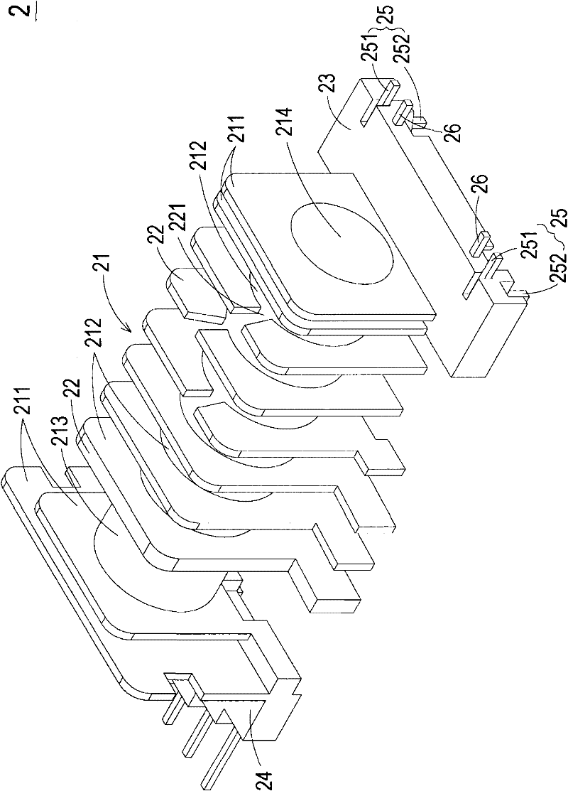
[0038] see figure 2 , which is a three-dimensional structural schematic diagram of a winding base suitable for a transformer structure according to a preferred embodiment of the present invention. like figure 2 As shown, the winding base 2 of the present invention is mainly suitable for a transformer structure, and can be used for winding a winding structure 3, such as primary winding or secondary winding, and the winding structure 3 has a wire outlet 31 And an initial winding place 32, the winding base 2 of the present invention at least includes a ma...


PUM


Abstract

The invention relates to a coiling base which is applicable to a transformer structure. The coiling base at least comprises a body and a plurality of connecting seats, wherein two opposite sides of the body are respectively provided with a side wall, and a coiling region is formed between the side walls and is used for winding a coiling structure; the connecting seats are respectively arranged ontwo opposite sides of the body and are connected with the side walls, and the bottoms of the connecting seats are provided with a plurality of wire sorting slots; and each side wall is provided with a concave slot which is communicated with the wire sorting slots, so that the start winding portions of the coiling structure are accommodated in the wire sorting slots and the concave slots to prevent the start winding portions from rubbing with the coiling structure subsequently wound in the coiling region. Through the coiling base, the friction between the start winding portions and the coilingstructure subsequently wound in the coiling region is prevented, and the fracture of the wire outgoing end of the coiling structure can be prevented. In addition, the efficacy of preventing tin solders welded on two adjacent connecting portions from being connected can be achieved.

Description

technical field [0001] The invention relates to a winding base, in particular to a winding base suitable for a transformer structure. Background technique [0002] Transformer is a magnetic component often used in various electrical equipment. It uses the principle of electric energy and magnetic energy conversion induction to adjust different voltages to make it reach the applicable range of electrical equipment. [0003] see Figure 1A , which is a structural schematic diagram of a known transformer. As shown in the figure, the transformer 1 includes a winding base 11 (bobbin), a cover 12 (cover) and a magnetic core assembly 13 (magnetic core assembly), wherein a primary winding coil 111 (primary winding coil) and a secondary winding coil 112 (secondary winding coil) is wound on the winding base 11, and its outlet ends 113, 114 are then wound and welded on the connecting portion 117, while the other end of the plug-in portion 115 is plugged into a system circuit board (no...

Claims


Application Information

Patent Timeline
IPC IPC(8): H01F41/06H01F41/098
Inventor 蔡辛卫陈义霖田庆相陈帝之
Owner DELTA ELECTRONICS INC
Features
  • Generate Ideas
  • Intellectual Property
  • Life Sciences
  • Materials
  • Tech Scout
  • Unparalleled Data Quality
  • Higher Quality Content
  • 60% Fewer Hallucinations
Learn More