
Deep hole drilling machine

A deep hole drilling machine, bed technology, applied in the direction of boring/drilling, drilling/drilling equipment, parts of boring machine/drilling machine, etc. problems such as poor stability, compact structure, stable clamping and reliable positioning

Active Publication Date: 2011-09-28
ZHEJIANG XILING
View PDF7 Cites 25 Cited by
  • Summary
  • Abstract
  • Description
  • Claims
  • Application Information

AI Technical Summary

Problems solved by technology

However, the existing problems are: 1. Poor orientation and stability, and the stability of the tool during processing is not high; 2. Only the drill rod rotates during processing, and the processing accuracy and efficiency are not high; 2. The structure of the existing deep hole drilling machine is not enough Compact and takes up a lot of space

Method used


Image

  • Deep hole drilling machine
  • Deep hole drilling machine
  • Deep hole drilling machine

Examples


Embodiment 1

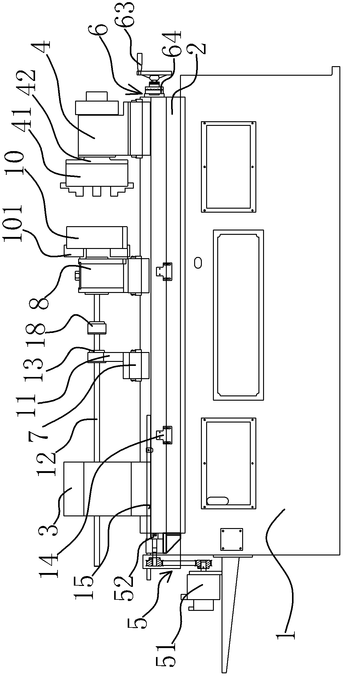
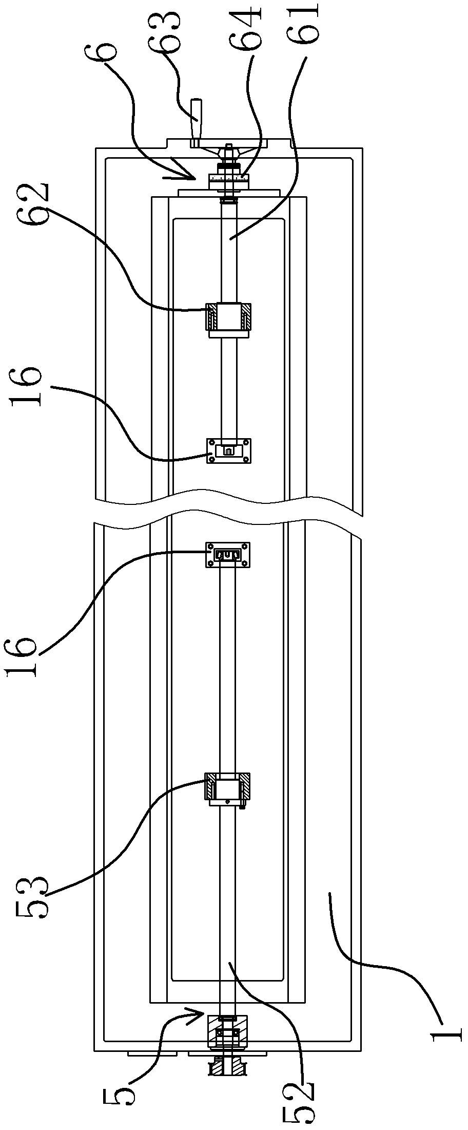
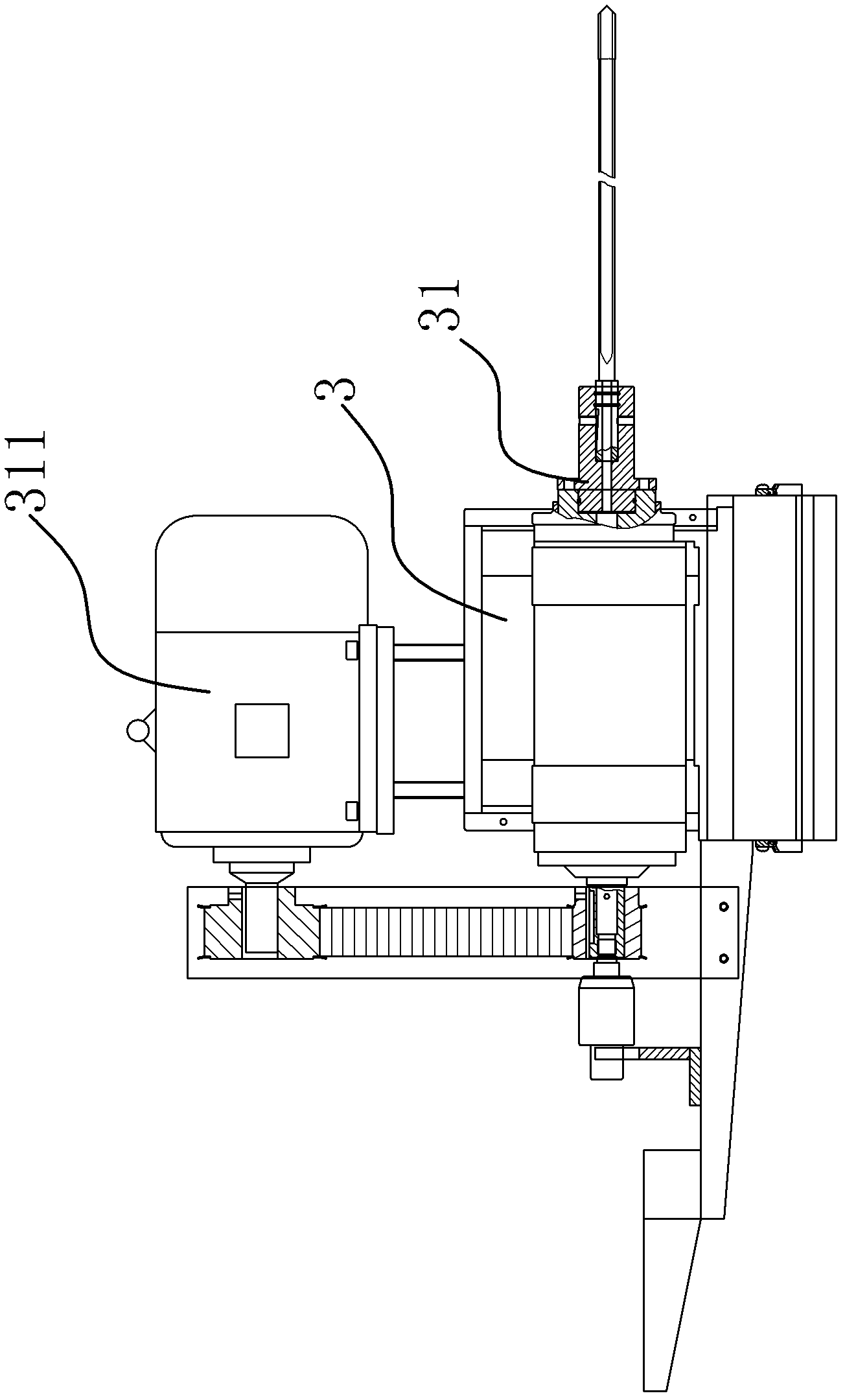
[0032] This deep hole drilling machine is used for deep hole processing of workpieces, including bed 1, slide rail 2, power head 3 and tailstock 4. Such as figure 1 , figure 2 with image 3 As shown, the tailstock 4 and the power head 3 are arranged on the slide rail 2, the power head 3 is provided with a feed spindle 31, the tailstock 4 is provided with a rotating spindle 42, and a driving mechanism is provided between the power head 3 and the bed 1 15. A driving mechanism 26 is provided between the tailstock 4 and the bed 1.

[0033] Such as figure 1 , figure 2 with image 3 As shown, in the present embodiment, the driving mechanism one 5 includes a driving motor two 51, a screw mandrel one 52 and a screw nut one 53, the driving motor two 51 is fixed on the motor bracket of the bed 1, and the screw mandrel one 52 passes through the positioning seat 16 Axial positioning with bed 1. Driving motor two 51 is connected with screw mandrel one 52 by pulley transmission mec...

Embodiment 2

[0042] The technical solution of this embodiment is basically the same as the technical solution of Embodiment 1, the difference is that in this embodiment, the driving mechanism 5 includes an oil cylinder and an oil supply mechanism, the cylinder body of the oil cylinder is fixed on the power head 3, and the cylinder body of the oil cylinder The end of the piston rod is fixed on the bed 1, and the oil supply mechanism communicates with the oil chamber of the oil cylinder. The oil cylinder is used to drive the power head 3 to feed, and the feed movement is stable.


PUM


Abstract

The invention provides a deep hole drilling machine which belongs to the technical field of machining equipment. The drilling machine solves the problems that the traditional deep hole drilling machine has poor guidance, poor stability, no high machining precision, no high efficiency and a not enough compact structure. The deep hole drilling machine comprises a lathe bed, a power head and a tailstock, wherein the lathe bed is provided with a horizontally arranged slide rail ; the tailstock and the power head are arranged on the slide rail; the power head is provided with a horizontally arranged feed main shaft and a driving motor I for driving the feed main shaft to rotate; one end of the feed main shaft can be connected with a cutting tool; a driving mechanism I is arranged between the power head and the lathe bed and can drive the power head to slide along the slide rail; the tailstock is provided with a jig; and a driving mechanism II is arranged between the tailstock and the lathe bed and can drive the tailstock to slide along the slide rail. The lathe bed of the deep hole drilling machine is provided with the driving mechanism I for driving the power head to slide along the slide rail and the driving mechanism II for driving the tailstock to slide along the slide rail, so that the design is reasonable and the structure is compact; moreover, the lathe bed is provided withthe guide rail and a guide holder, thereby the machining precision of deep holes is improved.

Description

technical field [0001] The invention belongs to the technical field of mechanical processing equipment, and relates to a deep hole drilling machine, in particular to a horizontal numerically controlled deep hole drilling machine. Background technique [0002] The deep hole drilling machine is a machine tool that uses a special deep hole drill bit, the drill bit moves in a straight line, and the workpiece rotates to drill deep holes. Different from traditional deep hole processing equipment, deep hole drilling machines rely on specific drilling technology to drill deep hole systems and precision shallow holes with a length-to-diameter ratio greater than 10, with high precision, high efficiency and high consistency The advantages. According to the layout of the main shaft, the deep hole drilling machine can be divided into horizontal deep hole drilling machine, vertical deep hole drilling machine and three-coordinate deep hole drilling machine. With the advancement of scienc...

Claims


Application Information

Patent Timeline
Patent Type & Authority Applications(China)
IPC IPC(8): B23B41/02B23B47/18B23B47/00
Inventor 周红亮张友为
Owner ZHEJIANG XILING
Learn More