Full-automatic pipe repair equipment
A fully automatic, pipe technology, used in other manufacturing equipment/tools, manufacturing tools, etc., can solve problems such as low efficiency, difficult to polish, affect appearance, etc., and achieve the effect of broad market prospects and great economic value
- Summary
- Abstract
- Description
- Claims
- Application Information
AI Technical Summary
Problems solved by technology
Method used
Image

Examples
Embodiment 2
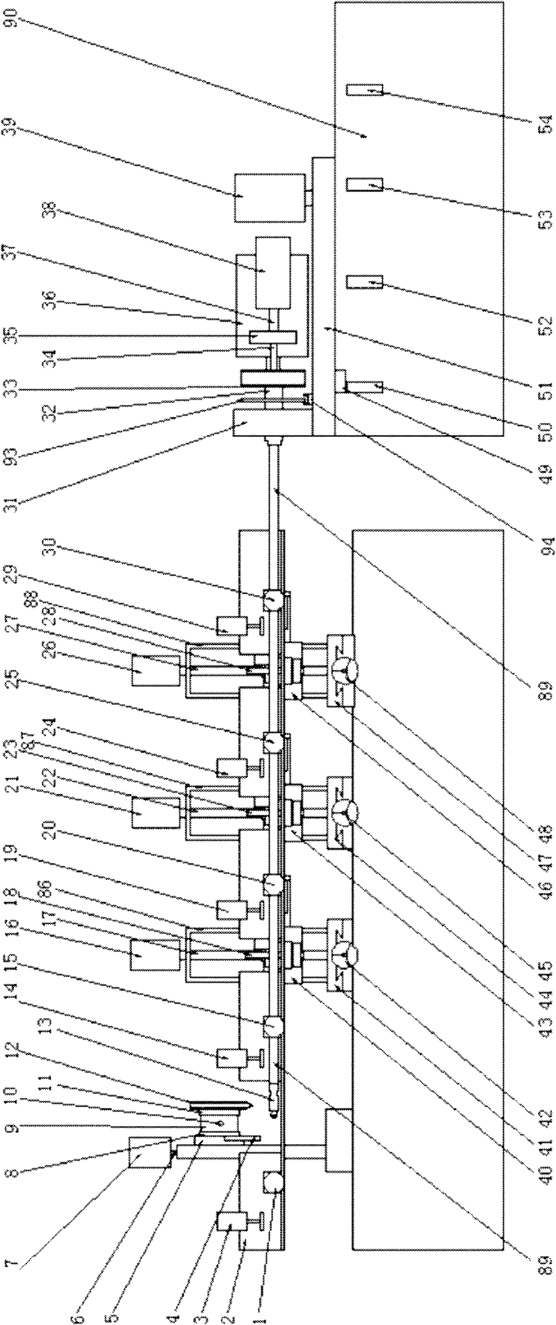
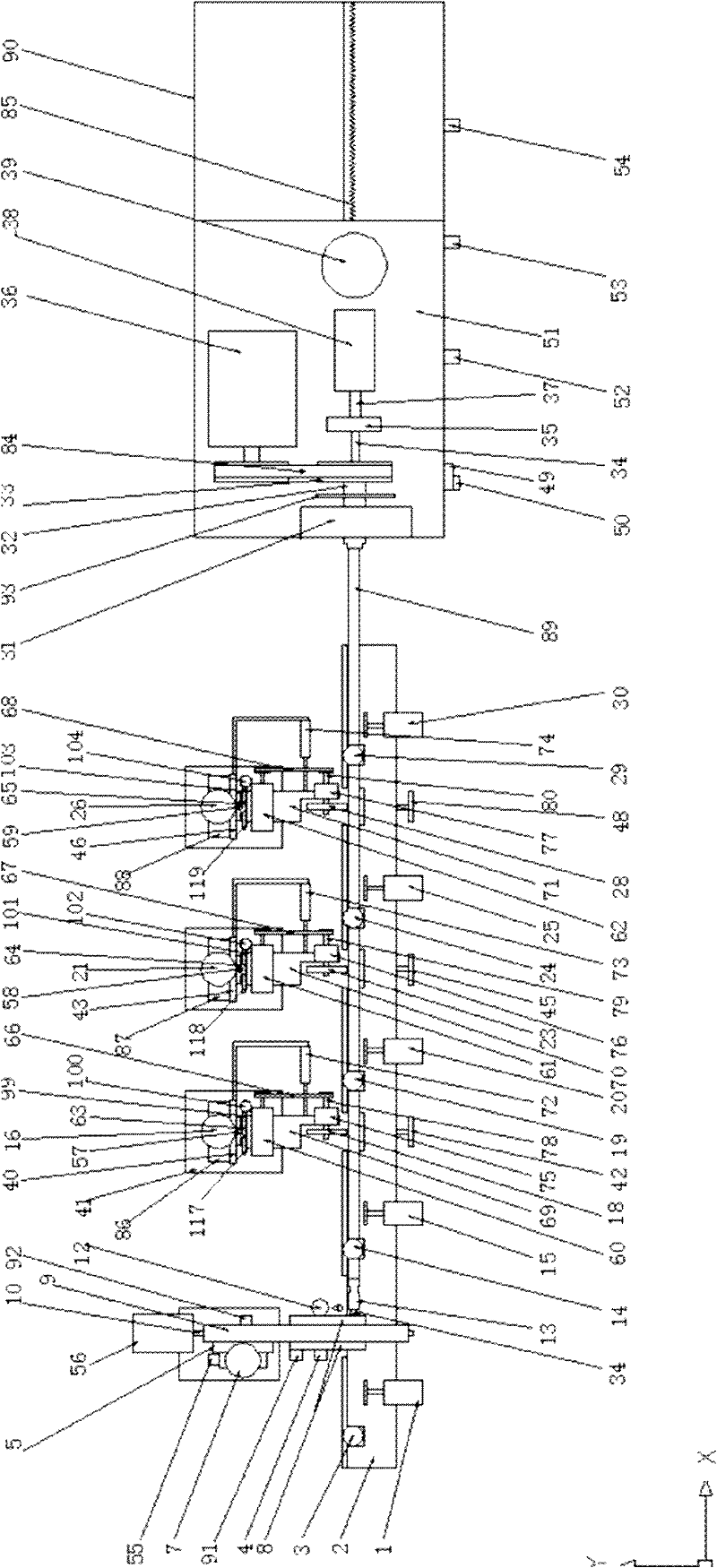
[0059] The workflow of embodiment 2 square (moment) pipe automatic repair (see figure 1 figure 2 ):
[0060] When the control circuit was switched to the square (moment) working state, at first, the grinding head reversing device in the curve grinding mechanism worked, so that the whole equipment was in the square (moment) tube repair state. Taking the curve grinding mechanism where the grinding head (18) is located as an example, the rotating cylinder (100) shrinks, drives the rotating plate (99) to rotate 90 degrees through the connecting piece (106), and simultaneously drives the rocker arm fixed on the rotating plate to rotate 90 degrees synchronously. degrees, so that the plane where the grinding head rotates is parallel to the axis of the tube.
[0061]Then after the welding position of the first face of the two sections of square tubes is aligned on the expansion block (13), the working circuit is started, and the cylinder (3), (14), (19), (24), (29), ( 1), (15), (4...
Embodiment 3
[0070] Embodiment 3: The position of the weld seam (109) does not move, and the stroke mechanism pushes the automatic welding torch mechanism and several curve grinding mechanisms to continuously pass through the weld seam of the pipe (see Figure 5 Figure 7 Figure 8 )
[0071] There are several ways for the stroke mechanism to make the welding seam move relative to the automatic welding torch mechanism and several curve grinding mechanisms. The travel mechanism pushes and pulls the welding seam through the transmission device, and the position of the welding seam is moving. exist Figure 8 Among them, the position of the welding seam (109) remains unchanged, but the positions of the automatic welding torch mechanism and several curve grinding mechanisms have changed. This embodiment is as follows:
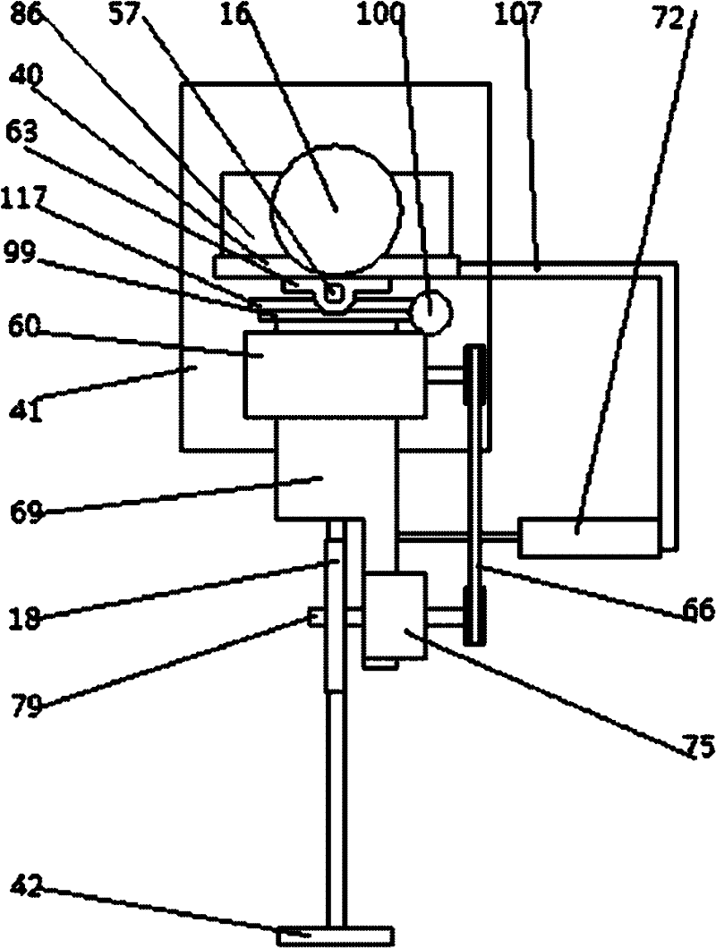
[0072] Figure 5 It is a schematic diagram of several main components in the curve grinding mechanism, in Figure 8 The middle represents the curve grinding mechanism. F...
Embodiment 4
[0073] Embodiment 4: the distance between the grinding head and the weld (109) changes as a curve of "far → near → contact → near → far" (see Figure 5 , Figure 6 )
[0074] Figure 5 It is the main parts of the rocker mechanism: shaft (57), bearing housing (63), rocking plate (117), rotating plate (99), rotating cylinder (100), rocking arm (69) and grinding head (18), in Figure 6 The middle represents the rocker arm device, Figure 6 Among them, the rocker arm where the grinding head (18) is located is under the action of the cylinder, with the shaft (57) as the center of the circle, the weld (109) is reciprocally polished, and the path that the grinding head passes is from point A to point B to point C to Point D to point E. The distance from point A to the weld (109) is far, and the distance from point B to the weld (109) is short. The grinding head is in contact with the weld (109) at point C and is tangent to the weld (109). ) is short, and the distance to the weld...
PUM
 Abstract
Description
Claims
Application Information
 - Generate Ideas
- Intellectual Property
- Life Sciences
- Materials
- Tech Scout
- Unparalleled Data Quality
- Higher Quality Content
- 60% Fewer Hallucinations
Browse by: Latest US Patents, China's latest patents, Technical Efficacy Thesaurus, Application Domain, Technology Topic, Popular Technical Reports.
© 2025 PatSnap. All rights reserved.Legal|Privacy policy|Modern Slavery Act Transparency Statement|Sitemap|About US| Contact US: help@patsnap.com