
Dispersion optimization single-mode optical fibre for super-high-speed long-distance dense wave division multiplexing

A dense wavelength division multiplexing, single-mode fiber technology, applied in the field of optical communication, can solve problems such as large negative effects, complexity, and increased additional loss

Active Publication Date: 2011-09-28
TIANJIN XINMAO SCI & TECH
View PDF14 Cites 14 Cited by
  • Summary
  • Abstract
  • Description
  • Claims
  • Application Information

AI Technical Summary

Problems solved by technology

The refractive index distribution of non-zero dispersion-shifted fiber is more complex than that of standard single-mode fiber. When various types of fibers are fused together, the reflection and additional loss will often increase due to the differences in mode length diameter and fiber geometric parameters. , the longer the link, the more contacts, the greater the cumulative negative effect, which may cause an unacceptable bit error rate

Method used


Image

  • Dispersion optimization single-mode optical fibre for super-high-speed long-distance dense wave division multiplexing
  • Dispersion optimization single-mode optical fibre for super-high-speed long-distance dense wave division multiplexing
  • Dispersion optimization single-mode optical fibre for super-high-speed long-distance dense wave division multiplexing

Examples


Embodiment 1

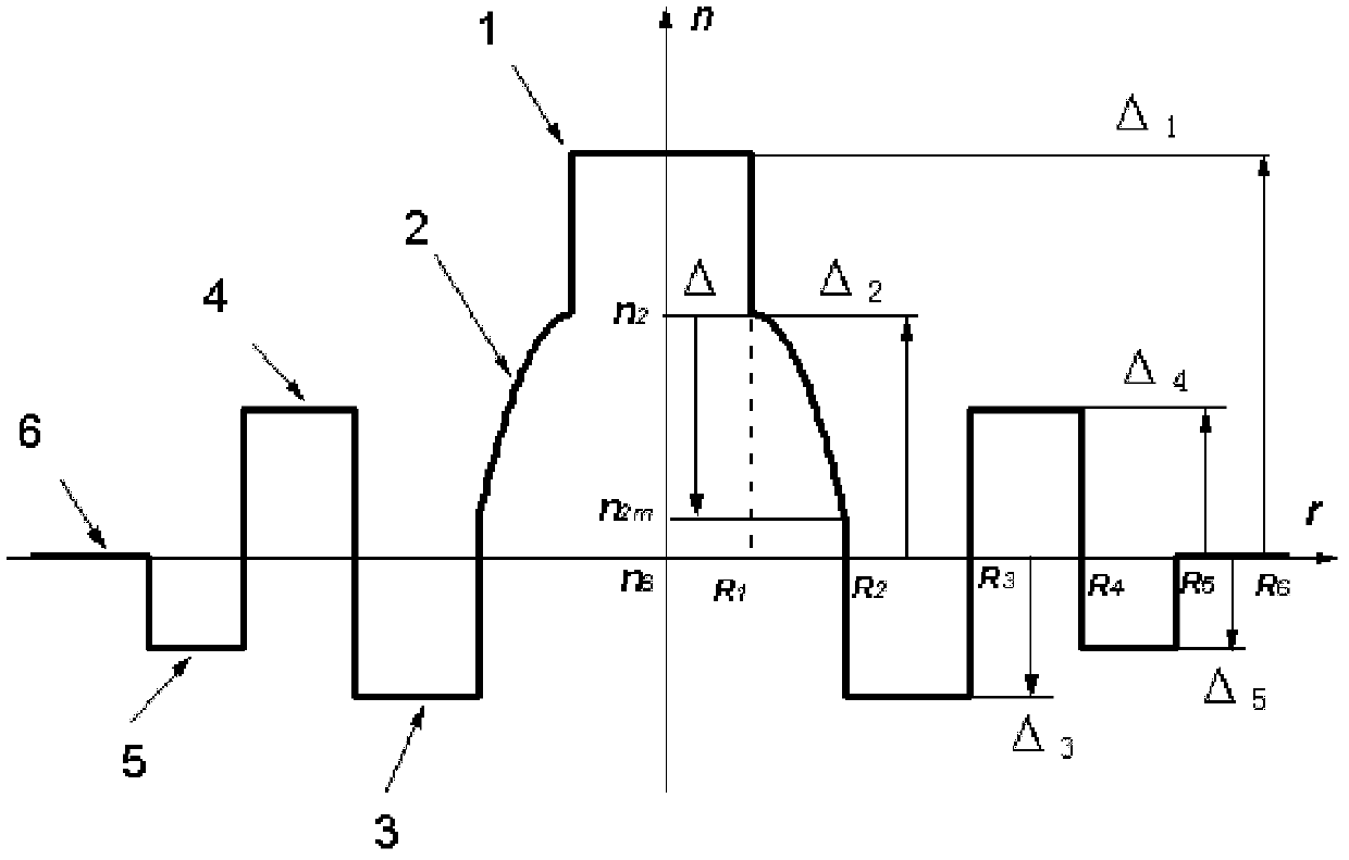
[0149] Such as figure 2 Shown is an optical fiber waveguide refractive index distribution curve of the present invention, and the numerals 1-6 represent six structural layers. The following is a set of refractive index increment, relative refractive index, and radius parameters:

[0150] The parameters of the first layer are: Δ 1 =0.58%, |r|≤1.85um;

[0151] The parameters of layer 2 are: Δ 2 =0.18%, 1.85um<|r|≤3.85um;

[0152] Δ=0.22%, α=1.3;

[0153] The parameters of layer 3 are: Δ 3 =-0.13%, 3.85um<|r|≤5.75um;

[0154] The parameters of layer 4 are: Δ 4 =0.18%, 5.75um<|r|≤8.35um;

[0155] The parameters of layer 5 are: Δ 5 =-0.03%, 8.35um<|r|≤9.35um;

[0156] The parameters of layer 6 are: Δ 6 =0 9.35 um<|r|≤62.5 um;

[0157] The properties of the resulting fiber are as follows:

[0158] 1550nm dispersion slope is 0.083 ps / (nm 2 km);

[0159] The zero dispersion wavelength is 1613.1 nm;

[0160] The effective area is 72.1um 2 ;

[0161] The dispersion at...

Embodiment 2

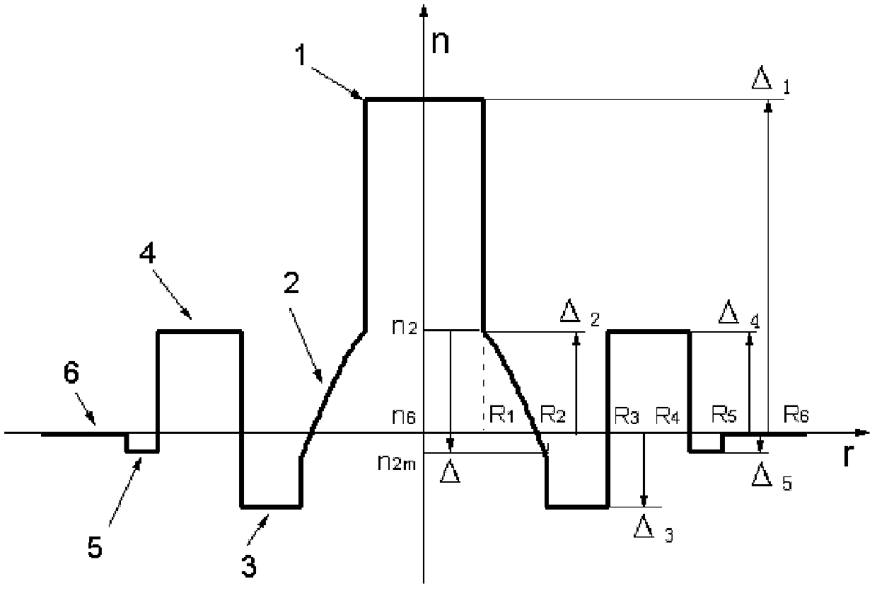
[0172] according to image 3 The shown optical fiber waveguide refractive index distribution curve, numbers 1-6 represent six structural layers, the following is a set of refractive index increment, relative refractive index, radius parameters:

[0173] The parameters of the first layer are: Δ 1 =0.40%, |r|≤3.5um;

[0174] The parameters of layer 2 are: Δ 2 =0.35%, 3.5um<|r|≤4.1um;

[0175] Δ=0.49%, α=1.1;

[0176] The parameters of layer 3 are: Δ 3 =-0.48%, 4.1 um<|r|≤5.7 um;

[0177] The parameters of layer 4 are: Δ 4 =0.34%, 5.7um<|r|≤8.3um;

[0178] The parameters of layer 5 are: Δ 5 =-0.17% 8.3 um<|r|≤9.3 um;

[0179] The parameters of layer 6 are: Δ 6 =0 9.3 um<|r|≤62.5 um;

[0180] The properties of the resulting fiber are as follows:

[0181] 1550nm dispersion slope is 0.05 ps / (nm 2 km);

[0182] The zero dispersion wavelength is 1434 nm;

[0183] Active area is 72 um 2 ;

[0184] The dispersion at 1550nm is 5.68 ps / (nm km);

[0185] The mode field diam...

Embodiment 3

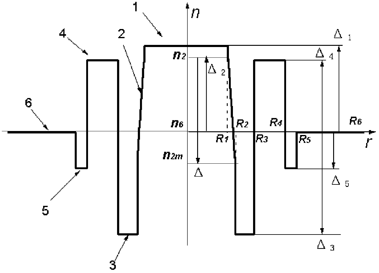
[0191] according to Figure 4 The shown optical fiber waveguide refractive index distribution curve, numbers 1-6 represent six structural layers, the following is a set of refractive index increment, relative refractive index, radius parameters:

[0192] The parameters of the first layer are: Δ 1 =0.42%, |r|≤2.7um;

[0193] The parameters of layer 2 are: Δ 2 =0.38%, 2.7um<|r|≤3.9um;

[0194] Δ=0.50%, α=1.4;

[0195] The parameters of layer 3 are: Δ 3 =-0.17%, 3.9 um<|r|≤5.5 um;

[0196] The parameters of layer 4 are: Δ 4 =0.21%, 5.5um<|r|≤8.1um;

[0197] The parameters of layer 5 are: Δ 5 =-0.20% 8.1 um<|r|≤9.1 um;

[0198] The parameters of layer 6 are: Δ 6 =0 9.1 um<|r|≤62.5 um;

[0199] The properties of the resulting fiber are as follows:

[0200] 1550nm dispersion slope is 0.0667 ps / (nm 2 km);

[0201] The zero dispersion wavelength is 1430 nm;

[0202] Active area is 72 um 2 ;

[0203] The dispersion at 1550nm is 7.81 ps / (nm km);

[0204] The mode field...


PUM


Abstract

The invention discloses a dispersion optimization single-mode optical fibre for super-high-speed long-distance dense wave division multiplexing and belongs to an optical communication technology. A refractive index profile of the dispersion optimization single-mode optical fibre comprises six continuous structural layers with the distribution of different refractive indexes from the centre to the outside; and the distribution of the refractive indexes changes along with a radius. The refractive indexes are distributed sequentially from the centre to the outside like that: Delta 1, in which an absolute value of r is less than or equal to R1; Delta (r) = Delta ((r-R1) / (R2-R1)) <alpha>, in which the absolute value of r is more than R1 and less than or equal to R2; Delta 3, in which the absolute value of r is more than R2 and less than or equal to R3; Delta 4, in which the absolute value of r is more than R3 and less than or equal to R4; Delta 5, in which the absolute value of r is more than R4 and less than or equal to R5; and 0, in which the absolute value of r is more than R5 and less than or equal to R6, wherein r is the radius; Ri represents the maximum radius of the respective structural layers; i is equal to 1 to 6; Delta i is an increment of a maximum value of the refractive index of the i-th layer on the refractive index of the outermost layer; Delta (r) is a relative refractive index of the minimum refractive index of the radius r position of the second layer by reference of the maximum value of the refractive index of the second layer; Delta is the relative refractive index of a minimum value of the refractive index of the second layer by reference of the maximum value of the refractive index of the second layer; and alpha is a distribution factor and more than 0.

Description

technical field [0001] The invention belongs to the optical communication technology, and relates to a non-zero dispersion displacement single-mode optical fiber designed for a large-capacity, ultra-high-speed, and long-distance transmission system. The fiber has large mode field distribution (effective area), increased chromatic dispersion (positive or negative value) and lower dispersion slope, low loss, low polarization mode dispersion and excellent bending resistance, and Fiber splicing has the advantages of low splicing loss, etc. When it is applied to large-capacity, ultra-high-speed, long-distance dense wavelength division multiplexing DWDM system transmission, the large effective area and increased dispersion value are conducive to reducing nonlinear effects and low The excellent dispersion slope is conducive to comprehensive management of dispersion, flexible deployment of optical fiber links, and long-distance transmission in the C+L and S+C+L bands. Background tec...

Claims


Application Information

Patent Timeline
Patent Type & Authority Applications(China)
IPC IPC(8): G02B6/036G02B6/02
Inventor 吴金东吴雯雯李庆国孙可元李强
Owner TIANJIN XINMAO SCI & TECH
Learn More