Circulation radiator, and manufacturing method and components thereof

A technology for circulating heat dissipation and components, which is applied in electrical components, electric solid devices, semiconductor devices, etc., and can solve the problems of large heat sinks, increased cost, and limited heat transfer distance of heat pipes.

Active Publication Date: 2012-11-21
锘威科技(深圳)有限公司
View PDF0 Cites 0 Cited by
  • Summary
  • Abstract
  • Description
  • Claims
  • Application Information

AI Technical Summary

Problems solved by technology

The traditional way to enhance heat dissipation is to add heat pipes to the heat sink, use a strong fan to force convection, and weld more heat dissipation fins to increase the heat exchange area, but this method cannot be realized in the field of compact heat dissipation or long-distance heat dissipation. Because the heat transfer distance of the heat pipe is limited, and there is a limit to the heat transfer, the method of connecting multiple heat pipes in parallel will only make the cooling device huge and increase the cost

Method used


Image

  • Circulation radiator, and manufacturing method and components thereof
  • Circulation radiator, and manufacturing method and components thereof
  • Circulation radiator, and manufacturing method and components thereof

Examples


specific Embodiment approach

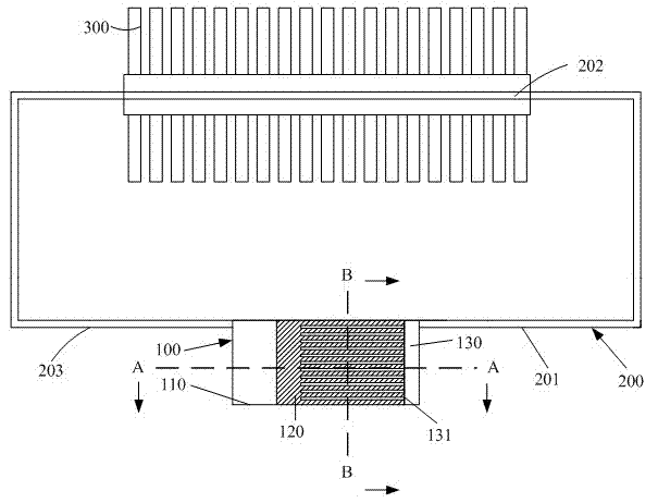
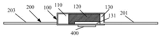
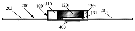
[0042] like Figure 8 As shown, a specific implementation of the manufacturing method of the circulating cooling device includes:

[0043] In the step of making capillary structure, a demoulding mold having at least one convex strip is inserted into the cavity with openings at both ends, and the cavity is filled with metal powder and / or nano-carbon powder and completely covers the convex strip of the demoulding mold. Sintering and extrusion of metal powder and / or nano-carbon powder to form a capillary structure;

[0044] In the demoulding step, the demoulding mold is pulled out, so that the capillary structure separates the cavity into a liquid storage cavity and an evaporation cavity having at least one steam channel;

[0045] Installation steps, connect one end of the pipeline with the liquid storage chamber or capillary structure, and connect the other end with the evaporation chamber, install the heat dissipation mechanism on the surface of the pipeline, and inject workin...


PUM


Abstract

The invention discloses a circulation radiator, and a manufacturing method and components thereof. The components of the circulation radiator comprise a pipeline, a heat dissipation mechanism and a vapor-liquid cavity; the heat dissipation mechanism is contacted with the pipeline, a capillary structure is arranged in the vapor-liquid cavity; the vapor-liquid cavity is divided into a liquid storage cavity and an evaporation cavity by the capillary structure; one end of the pipeline is connected with the evaporation cavity; the other end of the pipeline is connected with the liquid storage cavity or the capillary structure; the evaporation cavity comprises at least one steam channel; and the pipeline and the vapor-liquid cavity provide a low-pressure hermetic sealed channel. Compared with the prior art which employs one evaporation cavity, the invention has the advantages that: the whole capillary structure has stronger supporting force, so that the whole vapor-liquid cavity is difficult to deform and damage under the conditions of high temperature and high pressure; the evaporation cavity consisting of a plurality of the steam channels facilitates the evaporation of liquid in the evaporation cavity, so that vapor can reach a longer distance, heat dissipation of the long distance can be realized, a heat transfer limit based on the single-way circular flow of working fluid is greatly increased; and under the condition of the same heat dissipation and transfer capability, the vapor-liquid cavity provided by the scheme has lesser thickness, so that the volume of the radiator isreduced.

Description

technical field [0001] The invention relates to a circulating cooling device, its manufacturing method and its components. Background technique [0002] With the rapid development of electronic technology, the integration of transistors is getting higher and higher, and the heat generated by chips is increasing day by day, and electronic heat dissipation technology has gradually attracted attention. At present, the electronic heating problem has the following trends, the heat flux density is high, the heat dissipation space is narrow and compact, and heat dissipation is required across distances, such as the heat dissipation problem of high-power LEDs, CPUs, GPUs, and NOTEBOOKs. All of these require the development of efficient heat-conducting components to deal with the heat dissipation problem of the rapid development of electronic technology. The traditional way to enhance heat dissipation is to add heat pipes to the heat sink, use a strong fan to force convection, and w...

Claims


Application Information

Patent Timeline
Patent Type & Authority Patents(China)
IPC IPC(8): H01L23/367H01L23/427H01L21/48
Inventor 林梓荣张礼政
Owner 锘威科技(深圳)有限公司
Why Eureka
Try Eureka