
Method and system for positioning wireless sensor network

A wireless sensor and network positioning technology, applied in the transmission system, network topology, wireless communication and other directions, can solve the problems of low positioning accuracy and poor positioning speed, and achieve the effect of high positioning accuracy and fast positioning speed.

Inactive Publication Date: 2011-10-12
HARBIN INST OF TECH +1
View PDF2 Cites 16 Cited by
  • Summary
  • Abstract
  • Description
  • Claims
  • Application Information

AI Technical Summary

Problems solved by technology

[0004] The present invention aims to solve the problems of poor positioning speed and low positioning accuracy of existing wireless sensor network positioning systems or methods, thereby providing a wireless sensor network positioning system and positioning method

Method used


Image

  • Method and system for positioning wireless sensor network
  • Method and system for positioning wireless sensor network
  • Method and system for positioning wireless sensor network

Examples


specific Embodiment approach 1

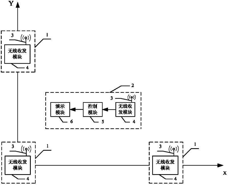
[0029] Specific implementation mode 1. Combination figure 1 and figure 2 Describe this specific embodiment, a wireless sensor network positioning system, which includes three beacon nodes 1, the structure of each of the beacon nodes 1 is exactly the same, all composed of a wireless transceiver antenna 3 and a wireless transceiver module 4 , the signal receiving end or the signal transmitting end of the wireless transceiver antenna 3 is connected with the signal transmitting end or the receiving end of the wireless transceiver module 4;

[0030] The wireless sensor network node 2 to be tested includes a wireless transceiver antenna 3, a wireless transceiver module 4 and a control module 5, the signal receiving end or the signal transmitting end of the wireless transmitting and receiving antenna 3 is connected with the signal transmitting end or the receiving end of the wireless transceiver module 4, The signal output end of wireless transceiver module 4 is connected with the ...

specific Embodiment approach 2

[0034] Embodiment 2. The difference between this embodiment and the wireless sensor network positioning system described in Embodiment 1 is that the wireless sensor network node 2 to be tested also includes a demonstration module 6, and the signal input of the demonstration module 6 Terminal is connected with the signal output terminal of control module 5.

specific Embodiment approach 3

[0035] Embodiment 3. The difference between this embodiment and the wireless sensor network positioning system described in Embodiment 1 or 2 is that the control module in the wireless sensor network node 2 to be tested is realized by FPGA.

[0036] In this embodiment, the wireless transceiver module 4 of the wireless sensor network node 2 to be tested uses a USB port when transmitting data to the FPGA, and the chip used is CY7C68013. When the FPGA of the wireless sensor network node 2 to be tested transmits data to the computer, the RS232 serial port is used, and the baud rate is 19200;

[0037] In this embodiment, CC2510 is selected as the wireless transceiver module 4 of the wireless sensor network node 2 to be tested, and the XC2VP30 chip on the VirtexII-Pro development board is selected as the FPGA.


PUM


Abstract

The invention discloses a method and system for positioning a wireless sensor network, and the method and system can be used for solving the problems of low positioning speed and low positioning precision of the existing method and system for positioning the wireless sensor network. The distance between each beacon node and a node to be detected in the system is 1-10m. The method comprises the following steps: three beacon nodes respectively utilize self IDs, data length, target addresses, data, zone bits and the like to form data frames, and the data frames are periodically broadcast in a CSMA (Carrier Sense Multiple Access) mode; the node to be detected receives broadcast signals from the three beacon nodes as well as stores and analyzes the structure of each part of each data frame; an RSSI (Received Signal Strength Indicator) value is read, the distance between a wireless sensor network node to be detected and each three beacon node is obtained through calculation by an RSSI-distance linear transformation model; and then, the coordinate of the node to be detected is obtained by virtue of trilateration so as to position the wireless sensor network node. The method and the system are suitable for positioning the wireless sensor network node.

Description

technical field [0001] The invention relates to a wireless sensor network positioning system and a positioning method. Background technique [0002] Wireless sensor network (WSN) is a brand-new information acquisition and processing technology, which can monitor, perceive and collect information of various environments or monitoring objects in real time, and has flexibility, fault tolerance, high perception ability, low cost and rapid layout, etc. Features, widely used in national defense and military, environmental monitoring and forecasting, medical and health, space exploration and other fields. Many specific applications in WSN rely on the geographic location information of sensor nodes or target objects. The sensor node must know its own position in order to specify in what position or area a specific event has occurred, so as to realize the positioning and tracking of external targets. [0003] The research on WSN's own positioning system and positioning method has r...

Claims


Application Information

Patent Timeline
Patent Type & Authority Applications(China)
IPC IPC(8): H04W64/00H04W84/18H04B17/00
Inventor 胡心怡许震宇许书彬石硕吴少川张国忠江晓林张明洋
Owner HARBIN INST OF TECH
Features
  • Generate Ideas
  • Intellectual Property
  • Life Sciences
  • Materials
  • Tech Scout
  • Unparalleled Data Quality
  • Higher Quality Content
  • 60% Fewer Hallucinations
Learn More