
X-ray ct apparatus, and its method

一种CT图像、被检测体的技术,应用在测量装置、诊断、应用等方向,能够解决透过长度变长、未公开结构、无视生物体吸收等问题

Active Publication Date: 2011-10-12
KYOTO UNIV +1
View PDF5 Cites 8 Cited by
  • Summary
  • Abstract
  • Description
  • Claims
  • Application Information

AI Technical Summary

Problems solved by technology

In this case, if the X-ray transmission length becomes longer due to the larger living body, the absorption of X-rays by the living body cannot be ignored, so the effect of the contrast agent will be reduced
In addition, if the amount of X-rays is to be increased, it is generally achieved by increasing the voltage applied to the X-ray tube (X-ray tube voltage), so that the high-energy components of the X-rays irradiated to the living body increase.
Therefore, the X-rays absorbed by the contrast agent will be reduced
[0008] Moreover, although the patent document 1 (D1) describes that the X-ray imaging method disclosed in the patent document 1 (D1) can be applied to CT (paragraph [0078]), the specific details are not disclosed. structure, and as its effect, only a reduction in the radiation dose of X-rays can be predicted

Method used


Image

  • X-ray ct apparatus, and its method
  • X-ray ct apparatus, and its method
  • X-ray ct apparatus, and its method

Examples


Embodiment Construction

[0024] Hereinafter, an embodiment according to the present invention will be described with reference to the drawings. In addition, the structures to which the same code|symbol is attached|subjected in each figure represent the same structure, and the description is abbreviate|omitted.

[0025] (Structure of embodiment)

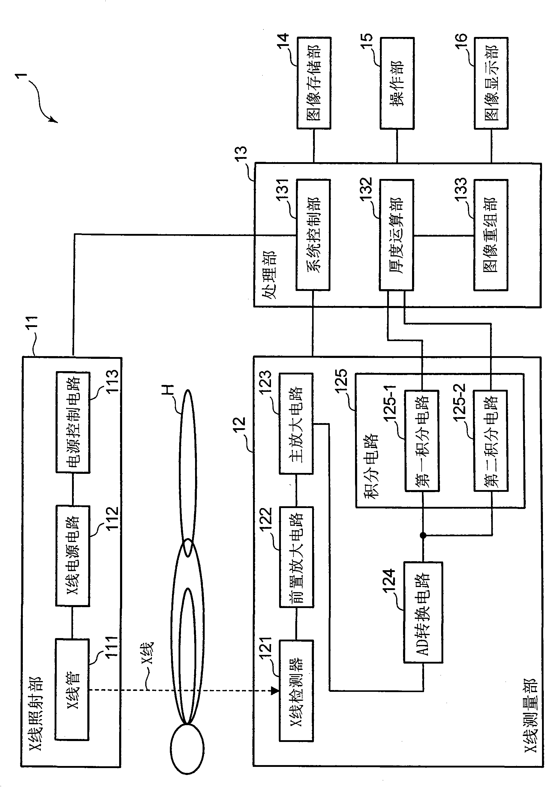
[0026] figure 1 It is a block diagram showing the configuration of the X-ray CT apparatus in one embodiment of the present invention. figure 1 Among them, the X-ray CT apparatus 1 includes an X-ray irradiation unit 11 , an X-ray measurement unit 12 , a processing unit 13 , an image storage unit 14 , an operation unit 15 , and an image display unit 16 .

[0027] The X-ray irradiation unit 11 is a device for irradiating X-rays, and includes, for example: an X-ray tube 111, which is used to generate and emit X-rays; an X-ray power supply circuit 112, in order to make the X-ray tube 111 generate X-rays, inputting commercial power, etc. After the voltage is boo...


PUM


Abstract

In an X-ray CT apparatus (1) and an X-ray CT method, the thickness of an inspection object is computed on the basis of the number of transmission X-rays in a specific energy range set by the upper and lower K-absorption ends of an X-ray contrast media acting as the inspection object, and a CT image is reconstituted on the basis of the computed thickness of the inspection object. These X-ray CT apparatus (1) and X-ray CT method can create the X-ray CT image stably independently of the magnitude of the inspection object and the X-ray tube voltage (or the energy distribution of the X-ray).

Description

technical field [0001] The present invention relates to an X-ray CT device and an X-ray CT method, in particular to an X-ray CT device and an X-ray CT method for generating CT images according to energy information of transmitted X-rays. Background technique [0002] Image diagnosis based on X-ray transmission or image diagnosis based on X-ray CT (Computed Tomography, computerized tomography) can find lesions such as cancer or ulcer inside the subject, so it is used as an effective diagnostic method . In these image diagnoses, the dose of X-rays transmitted through the subject (or the dose of X-rays absorbed by the subject) is measured, and an X-ray image is generated by graphically expressing the increase or decrease of the dose . Since the elements constituting living organisms are relatively light elements such as hydrogen, nitrogen, oxygen, and calcium, the absorption coefficient of X-rays is small. Therefore, in order to generate a clear X-ray image when a living bod...

Claims


Application Information

Patent Timeline
Patent Type & Authority Applications(China)
IPC IPC(8): A61B6/03
CPCA61B6/032A61B6/4035A61B6/4042A61B6/405A61B6/4241A61B6/481A61B6/482A61B6/504A61B6/544A61B6/583G01N23/087G01N23/046
Inventor 神野郁夫
Owner KYOTO UNIV
Learn More