Tubular/cylindrical mud residue internal reflux mud-water high-efficiency separation device

A separation device and internal reflux technology, which is applied to the feeding/discharging device, separation method, sedimentation separation and other directions of the sedimentation tank, can solve the problems of insufficient space utilization, easy blockage of the reflux seam, and large floor space. Complete and reasonable energy utilization, lower operating costs, and the effect of reducing floor space

Inactive Publication Date: 2011-10-19
CHONGQING UNIV
View PDF5 Cites 14 Cited by
  • Summary
  • Abstract
  • Description
  • Claims
  • Application Information

AI Technical Summary

Problems solved by technology

[0003] 1. The concentration of reflux active sludge is small, resulting in a large area occupied by the clarifier
Due to the small concentration of active sludge returned in ordinary mechanically accelerated clarifiers, the required return flow of active sludge is generally 3-5 times that of the influent flow, so that the area of ​​the flocculation zone will be large, thereby increasing the overall The volume of the clarifier tank increases the cost and operating costs
[0004] 2. The problem of insufficient space utilization
Most of the water flow into the mechanically accelerated clarifier will not follow the design streamline trajectory: it enters the first flocculation zone from the triangular water distribution tank, and completes good flocculation in the first flocculation zone; instead, after the water is distributed by the triangular water distribution tank, it is directly passed by the impeller. The lifting device is lifted to the second flocculation zone, which shortens the flocculation time, affects the flocculation effect, leads to poor water quality, or increases the dosage of chemicals
[0005] 3. The backflow seam is easy to block
Many mechanically accelerated clarifiers in water plants have the phenomenon of blockage of the return slot. At the same time, in the process of designing the mechanically accelerated clarifier, the value of the return slot is also a problem that is difficult to determine
[0006] 4. High energy consumption
Due to the need to increase the amount of sludge 3-5 times the amount of water inflow, it needs to consume more energy and consumes more energy
[0007] Therefore, the mechanically accelerated clarifiers in actual operation have disadvantages such as insufficient space utilization, large amount of reflux sludge, large floor space, and high energy consumption.

Method used


Image

  • Tubular/cylindrical mud residue internal reflux mud-water high-efficiency separation device
  • Tubular/cylindrical mud residue internal reflux mud-water high-efficiency separation device
  • Tubular/cylindrical mud residue internal reflux mud-water high-efficiency separation device

Examples


Embodiment Construction

[0028] The present invention will be further described below in conjunction with the accompanying drawings.

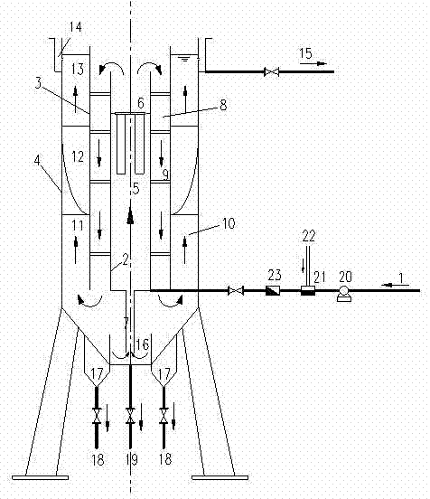
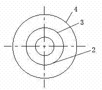
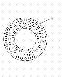
[0029] see figure 1 , figure 2 , image 3 , as can be seen from the figure, the device adopts a cylindrical stainless steel pool body, the upper part is cylindrical, and the lower part is truncated circular. The circular pool is isotropic, and the stress conditions and hydraulic conditions are very good. The interior of the device is mainly composed of mechanical flocculation area 5, hydraulic flocculation area 8, sedimentation area 10, sludge concentration chamber 16, active sludge return pipe / tube 7, small hole grid orifice plate 9 and inclined plate / pipe 12, etc. The exterior is mainly composed of a water inlet pipe 1, an outlet pipe 14, a mud bucket 17, a mud bucket mud discharge pipe 18, an emptying pipe 19 and a pool body.

[0030] The mechanical flocculation zone 5, the hydraulic flocculation zone 8, and the sedimentation zone 10 are concentric and separated...


PUM


Abstract

The invention relates to a small high-efficiency mud-water separation device used for supplying water to villages and small towns. The device comprises a mechanical flocculation area and a hydraulic flocculation area, a sedimentation area, an active mud residue concentration area, an active mud residue internal reflux tube/cylinder, an impeller lifting device, a water inlet and outlet system, a mud discharge system and the like. The main body of the device mainly comprises three layers of concentric cylinders; an inner cylinder is the mechanical flocculation area, the middle is provided with the impeller lifting device, and active mud residue at the bottom of a concentration chamber is lifted to the mechanical flocculation area by the internal reflux tube/cylinder arranged in the center of the bottom; the hydraulic flocculation area is formed between the inner cylinder and a middle cylinder, and is provided with a pore plate; the sedimentation area is formed between the middle cylinder and an outer cylinder, and is provided with a single-blade single-curve rotary sloping plate; and the bottom of the equipment is provided with a mud residue concentration chamber. The device has theadvantages of compact structure, high space utilization rate, small occupied area, mechanical flocculation area, easily controlled reflux quantity, low energy consumption, good effluent quality and the like, and has great promotion value.

Description

technical field [0001] The invention relates to the technical field of water supply, in particular to a mud-water separation device for small flow. Background technique [0002] The clarifier process is to integrate the two processes of flocculation and sedimentation into one structure, and mainly rely on active sludge to achieve the purpose of clarification. When the destabilized impurities come into contact with the active sludge layer along with the water flow, they are intercepted by the sludge layer to separate the sludge and water. At present, the most widely used clarifier in actual engineering is the mechanical acceleration clarifier, because the mechanical acceleration clarifier has the advantages of strong adaptability, stable operation, and good effluent quality. However, in the actual operation process, there are still many problems in the traditional mechanical acceleration clarifier, mainly including: [0003] 1. The concentration of backflow active sludge is...

Claims


Application Information

Patent Timeline
Patent Type & Authority Applications(China)
IPC IPC(8): B01D21/08B01D21/28B01D21/24
Inventor 蒋绍阶梁建军向平罗鑫臧守华王滔
Owner CHONGQING UNIV
Why Eureka
Try Eureka