Hydrocarbon conversion catalyst regeneration burning method and regenerator burning area structure

A technology of catalyst and coking zone, applied in the direction of catalyst regeneration/reactivation, physical/chemical process catalyst, chemical instruments and methods, etc., can solve problems such as the risk of flying temperature

Active Publication Date: 2011-10-19
CHINA PETROCHEMICAL CORP +1
View PDF6 Cites 9 Cited by
  • Summary
  • Abstract
  • Description
  • Claims
  • Application Information

AI Technical Summary

Problems solved by technology

[0009] The present invention aims at the disadvantages of overheating risk in the scorched zone of hydrocarbon conversion catalysts (such as reforming catalysts) in the prior art, and provides a new catalyst regeneration scorched method and scorched zone structure, which can be effectively avoided by using the present invention During the catalyst regeneration process, due to the failure to burn the residual carbon in time, when the oxygen content of the gas in the system suddenly increases, a sudden temperature will be generated near the inner net of Johnson in the upper part of the bed, resulting in damage to the Johnson net.

Method used


Image

  • Hydrocarbon conversion catalyst regeneration burning method and regenerator burning area structure
  • Hydrocarbon conversion catalyst regeneration burning method and regenerator burning area structure
  • Hydrocarbon conversion catalyst regeneration burning method and regenerator burning area structure

Examples


Embodiment Construction

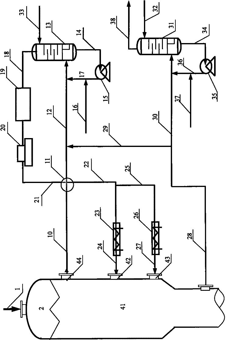
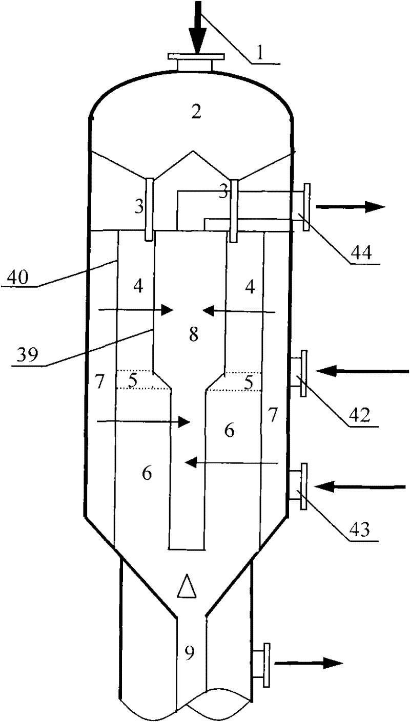
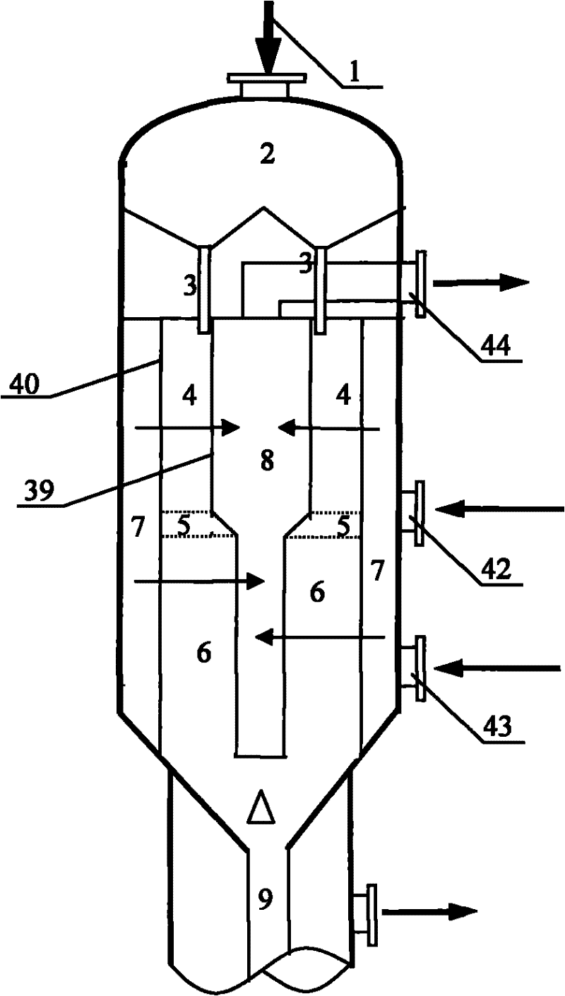
[0034] Such as figure 2 As shown, the catalyst bed layer in the coke area 41 of the regenerator is composed of a cylindrical inner screen 39 and a cylindrical outer screen 40, wherein the upper diameter of the inner screen 39 is larger than the lower diameter, and the upper and lower parts are separated by a Conical connection. The burnt zone 41 of the regenerator is located below the buffer zone 2 and communicated with the catalyst feeding leg 3 .

[0035] The cylindrical upper part of the inner screen 39 and the outer screen 40 constitute the upper fast-burning section 4 of the catalyst bed in the burnt zone, and the cylindrical lower part of the inner screen 39 and the outer screen 40 constitute the upper part of the catalyst bed in the burnt zone. The lower superheating section 6, the conical connection structure part of the inner screen 39 and the outer screen 40 constitute the intermediate transition section 5 of the catalyst bed in the burnt zone. The bed thickness r...


PUM


Abstract

The invention discloses a hydrocarbon conversion catalyst regeneration burning method and a regenerator burning area structure, and solves the problems that a hydrocarbon conversion catalyst burning area has a temperature runaway risk and the like in the prior art. The method comprises the following steps of: introducing a catalyst to be regenerated into a radial catalyst moving bed burning area by means of gravity, contacting oxygen-containing regeneration gas, and burning carbon deposit on the catalyst; and introducing into a chlorine oxidation area under the action of gravity, wherein a catalyst moving bed in the burning area is provided with a quick firing section, a transition section and a superheat section from top to bottom in turn; and the thickness ratio of catalyst beds in the quick firing section and the superheat section is 0.25-1 and the height ratio is 1-8.

Description

technical field [0001] The invention belongs to the field of petrochemical industry, and relates to a method for regenerating and burning a hydrocarbon conversion catalyst and a new structural form of the burning area of ​​a regenerator. Background technique [0002] Catalytic reforming is one of the important processes in oil refining and petrochemical industry. It is a hydrocarbon conversion process. Naphtha is used as raw material to generate reformed oil rich in aromatics through hydrogen catalytic reaction, and by-product hydrogen and liquefied petroleum gas. Reforming conversion is accompanied by carbon deposition reaction, deep dehydrogenation of hydrocarbons to generate olefins, olefin cyclization and polymerization to form condensed ring aromatics, which are adsorbed on the surface of the catalyst and finally form carbon deposition to deactivate the catalyst. The deactivated catalyst needs to be regenerated to restore its activity. The most important first step in ...

Claims


Application Information

Patent Timeline
Patent Type & Authority Applications(China)
IPC IPC(8): B01J38/26B01J38/20C10G35/12
Inventor 冯伟徐又春郭劲鹤易伍浪胡庆均韩江联
Owner CHINA PETROCHEMICAL CORP
Why Eureka
Try Eureka