

Small current grounding system single phase earth fault traveling wave line selection and distance measurement apparatus
A single-phase ground fault, small current grounding technology, applied in the field of power system, can solve the problems of being easily affected by interference signals, etc., and achieve the effect of wide application range and accurate measurement of fault distance
- Summary
- Abstract
- Description
- Claims
- Application Information
AI Technical Summary
Problems solved by technology
Method used
Image

Examples
Embodiment Construction
[0038] The present invention will be further described below in combination with specific embodiments and with reference to the accompanying drawings.
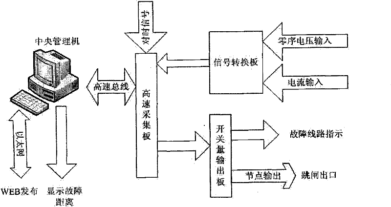
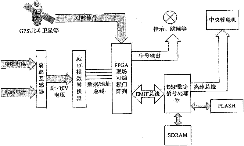
[0039] Working principle diagram of the present invention, as figure 1 shown. The signal conversion board converts the bus zero-sequence voltage and line current, including phase current and zero-sequence current, into 0-10 volt voltage signals through isolation, and transmits them to the high-speed acquisition board connected to the signal conversion board.
[0040] The high-speed acquisition board, after receiving the 0-10 volt voltage signal from the signal conversion board, converts the analog signal into a digital signal, and then performs high-speed acquisition and buffering. The high-speed acquisition board simultaneously receives the second pulse or B code and other time granted by GPS, Beidou satellite, etc. as the synchronous sampling signal of each device, and marks the data with absolute time scale. Then the DSP ...
PUM
 Abstract
Description
Claims
Application Information