Biochip incubation reactor

A bio-chip and reactor technology, which is applied in bioreactor/fermenter combinations, specific-purpose bioreactors/fermenters, biochemical instruments, etc. Simple and novel structure, the effect of reducing energy consumption

Inactive Publication Date: 2011-10-26
SUZHOU SJ BIOMATERIALS
View PDF4 Cites 43 Cited by
  • Summary
  • Abstract
  • Description
  • Claims
  • Application Information

AI Technical Summary

Problems solved by technology

However, the ultimate way to achieve high-intensity mixed incubations is to use an automated hybridiz

Method used


Image

  • Biochip incubation reactor
  • Biochip incubation reactor
  • Biochip incubation reactor

Examples


Embodiment 1

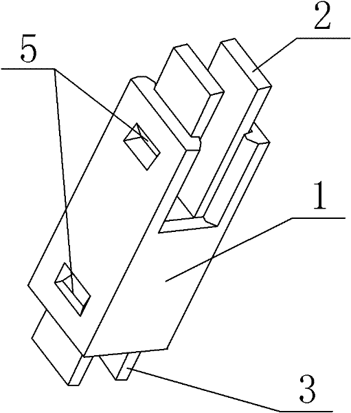
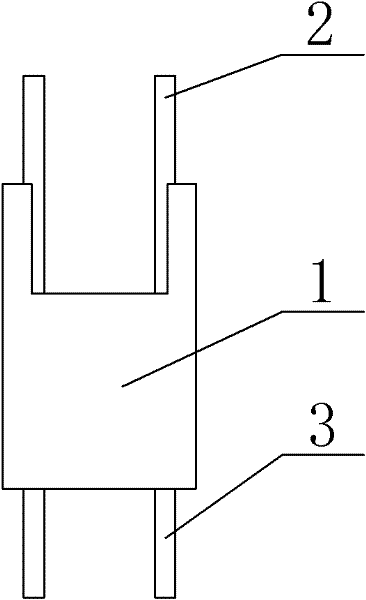
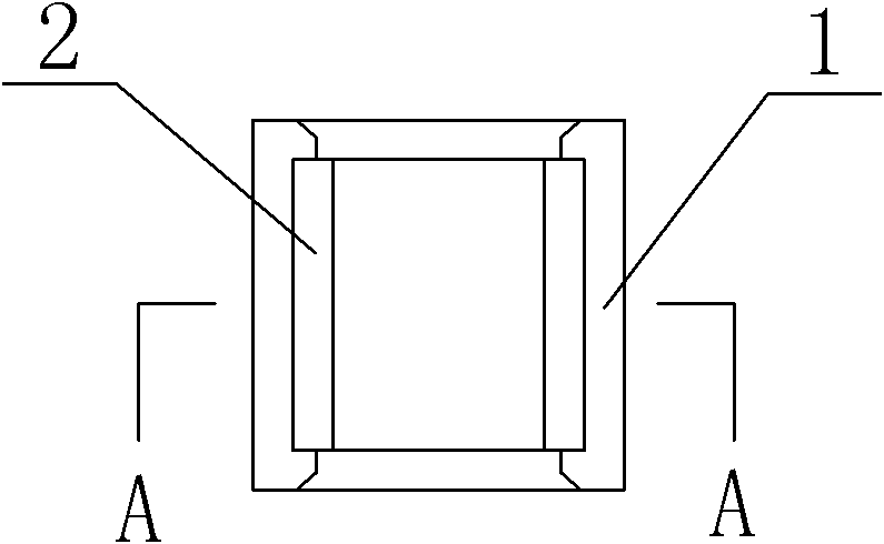
[0044] Such as figure 1 , figure 2 , image 3 with Figure 4The shown biochip incubation reactor comprises a reaction chamber 1, an upper cover plate 2 and a lower cover plate 3 symmetrically installed in the reaction chamber 1; a boss 4 is arranged on the inner wall of the reaction chamber 1, and the The boss 4 is integrally formed with the reaction chamber 1 and the boss 4 has a hollow structure as the incubation reaction chamber 6, and a gap for installing a biochip is provided between the lower cover surface of the upper cover plate 2 and the boss 4, so There is also a gap for installing biochips between the upper cover surface of the lower cover plate 3 and the boss 4; Contact; the gap between the lower cover surface of the upper cover plate 2 and the boss 4 is 0.2mm to 10mm, and the gap is preferably 0.2mm, 1.0mm, 2.0mm, 3.0mm, 4.0mm, 5.0mm, 6.0mm mm, 7.0mm, 8.0mm, 9.0mm, 10mm; the gap between the upper cover surface of the lower cover plate 3 and the boss 4 is 0.2m...

Embodiment 2

[0046] Such as Figure 5 , Image 6 , Figure 7 with Figure 8 The shown biochip incubation reactor comprises a reaction chamber 1, an upper cover plate 2 and a lower cover plate 3 symmetrically installed in the reaction chamber 1; a boss 4 is arranged on the inner wall of the reaction chamber 1, and the The boss 4 is integrally formed with the reaction chamber 1 and the boss 4 has a hollow structure as the incubation reaction chamber 6, and a gap for installing a biochip is provided between the lower cover surface of the upper cover plate 2 and the boss 4, so There is also a gap for installing biochips between the upper cover surface of the lower cover plate 3 and the boss 4; Contact; the gap between the lower cover surface of the upper cover plate 2 and the boss 4 is 0.2mm to 10mm, and the gap is preferably 0.2mm, 1.0mm, 2.0mm, 3.0mm, 4.0mm, 5.0mm, 6.0mm mm, 7.0mm, 8.0mm, 9.0mm, 10mm; the gap between the upper cover surface of the lower cover plate 3 and the boss 4 is 0....

Embodiment 3

[0048] Such as Figure 9 , Figure 10 , Figure 11 with Figure 12 The shown biochip incubation reactor comprises a reaction chamber 1, an upper cover plate 2 and a lower cover plate 3 symmetrically installed in the reaction chamber 1; a boss 4 is arranged on the inner wall of the reaction chamber 1, and the The boss 4 is integrally formed with the reaction chamber 1 and the boss 4 has a hollow structure as the incubation reaction chamber 6, and a gap for installing a biochip is provided between the lower cover surface of the upper cover plate 2 and the boss 4, so There is also a gap for installing biochips between the upper cover surface of the lower cover plate 3 and the boss 4; Contact; the gap between the lower cover surface of the upper cover plate 2 and the boss 4 is 0.2mm to 10mm, and the gap is preferably 0.2mm, 1.0mm, 2.0mm, 3.0mm, 4.0mm, 5.0mm, 6.0mm mm, 7.0mm, 8.0mm, 9.0mm, 10mm; the gap between the upper cover surface of the lower cover plate 3 and the boss 4 i...


PUM


Abstract

The invention discloses a biochip incubation reactor, comprising a reaction chamber, an upper cover plate and a lower cover plate that are symmetrically arranged in the reaction chamber. An inner wall of the reaction chamber is equipped with a boss which is molded in one body with the reaction chamber and has a hollow structure to be used as an incubation reaction chamber. A gap used for installing a biochip is arranged between a lower surface of the upper cover plate and the boss; and a gap used for installing a biochip is also arranged between an upper surface of the lower cover plate and the boss. The biochip incubation reactor of the present invention has a simple and novel structure, and is convenient for operation. During the reaction, solution volatilization can be avoided, and high strength oscillation can be realized, so as to increase reaction efficiency, reduce incubation time, and enhance experiment sensitivity, singularity and reappearance. Both the upper cover plate and the lower cover plate of the reactor can be pasted with biochips, so that incubation of double biochips can be completed simultaneously to save samples at least by half compared with a traditional method.

Description

technical field [0001] The invention belongs to the technical field of biochip reactors, in particular to a biochip incubation reactor. Background technique [0002] Biochip (biochip) technology is a highly integrated analytical technology developed in the early 1990s. According to its structural characteristics, it can be divided into two categories: microarray chips and microfluidic chips. Among them, the microarray chip is a chip composed of a biological material microarray, including DNA chips, protein chips, cell chips, and tissue chips. The sample molecules are subjected to an affinity binding reaction, and the number of target molecules in the sample is judged by detecting the strength of the signal amplified by enzymes, fluorescein or radioactive isotopes. The biochip integrates probe solid-phase in-situ synthesis technology, photolithography technology, polymer synthesis technology, precision control technology and laser confocal microscopy technology, enabling the...

Claims


Application Information

Patent Timeline
IPC IPC(8): C12M1/00
Inventor 马雄明
Owner SUZHOU SJ BIOMATERIALS
Why Eureka
Try Eureka