
Rectification grille for protecting fly ash particles on catalyst layer of SCR (Semiconductor Control Rectifier) denitration device

A technology of rectification grid and catalyst layer, which is applied in the separation of dispersed particles, chemical instruments and methods, separation methods, etc., can solve the problems of not improving the optimization design of rectifying grid, and not proposing CFD quantitative calculation of flue gas fly ash particles.

Active Publication Date: 2011-11-02
上海电气电站环保工程有限公司 +1
View PDF3 Cites 14 Cited by
  • Summary
  • Abstract
  • Description
  • Claims
  • Application Information

AI Technical Summary

Problems solved by technology

However, this paper did not improve the optimal design of the parameters of the rectifying grid from the perspective of protecting the catalyst layer, especially the influence of the height and installation position of the rectifying grid on the direction distribution of the flue gas velocity vector above the catalyst layer based on the flow field distribution and the There is no CFD quantitative calculation of the erosion of the catalyst layer by the flue gas fly ash particles passing through the rectification grid

Method used


Image

  • Rectification grille for protecting fly ash particles on catalyst layer of SCR (Semiconductor Control Rectifier) denitration device
  • Rectification grille for protecting fly ash particles on catalyst layer of SCR (Semiconductor Control Rectifier) denitration device
  • Rectification grille for protecting fly ash particles on catalyst layer of SCR (Semiconductor Control Rectifier) denitration device

Examples


Embodiment Construction

[0019] The embodiments of the present invention are described in detail below. This embodiment is implemented on the premise of the technical solution of the present invention, and detailed implementation methods and specific operating procedures are provided, but the protection scope of the present invention is not limited to the following implementation example.

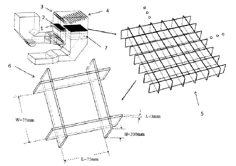
[0020] like figure 1 and figure 2 As shown, it is the overall flue and rectifying grille part of the SCR denitrification device of a 300MW thermal power station, and the outer wall size of the flue is 15750×11400×200mm.

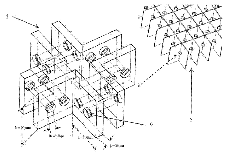
[0021] The rectifying grid 5 described in this embodiment is located at the 5mm-10mm place on the upper surface of the catalyst layer 7 and is composed of several cuboid grid units 6. It is composed of L-shaped angle iron 8; the rectifying grid is fixedly supported on the wall of the flue of the SCR denitrification system by the grid support beam.

[0022] The L-shaped angle iron 8 in the cub...


PUM

PropertyMeasurementUnit
Thicknessaaaaaaaaaa
Diameteraaaaaaaaaa
Heightaaaaaaaaaa

Abstract

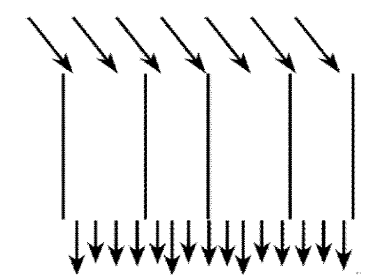
The invention provides a rectification grille for protecting fly ash particles on a catalyst layer of an SCR (Semiconductor Control Rectifier) denitration device, belonging to the technical field of selective catalytic reduction and denitration. The rectification grille comprises cuboid grille units and a grille supporting beam, wherein the rectification grille is located at a position 5mm-10mm away from an upper surface of the catalyst layer, and consists of a plurality of cuboid grille units, each cuboid grille unit consists of a plurality of longitudinally and transversely vertical steel plates and four L-shaped angle irons, and the L-shaped angle irons are fixed to joints of the steel plates; and the rectification grille is fixedly supported on a wall surface of a flue of an SCR denitration system through the grille supporting beam. According to the invention, flue gases with a certain included angle with the vertical circulation direction before entering the rectification grille are subjected to gas-gas turbulent dissipation and gas-solid collision in each cuboid grille unit of the rectification grille, and the flue gases out of the rectification grille substantially flow downwards vertically, so that the catalyst wall surface at the lower side is prevented from being washed and eroded by solid particles, and thereby the catalyst blockage and inactivation are avoided.

Description

technical field [0001] The invention relates to a device in the technical field of selective catalytic reduction (SCR) denitrification, in particular to a rectifying grid used for protecting fly ash particles in a catalyst layer of an SCR denitrification device. Background technique [0002] Flue gas denitration methods include selective catalytic reduction (SCR) technology, selective non-catalytic reduction (SNCR) technology, SNCR / SCR combined flue gas denitrification technology, as well as liquid absorption method, microbial absorption method, activated carbon adsorption method, electron beam method, etc. . At present, the most widely used and most effective flue gas denitrification mainstream technology is SCR technology, and its denitrification efficiency is above 80%. The main principle of the selective catalytic reduction method is to use ammonia (NH 3 ) as a reducing agent and nitrogen oxides (NO x ) redox reaction occurs under the action of the catalyst to generat...

Claims


Application Information

Patent Timeline
IPC IPC(8): B01D53/90B01D53/56
Inventor 金强张硕袁景淇林钢李雨许媛媛张善伟刘凤娜李林涛王景成
Owner 上海电气电站环保工程有限公司
Learn More