
Method and equipment for realizing low-temperature thermal power generation by cryogenic technology

A thermal power generation and low temperature technology, which is applied in the fields of thermal power, environmental protection, power generation, refrigeration, machinery manufacturing and automation, and can solve the problems of stable heat source and limitation of the selection of refrigerants.

Inactive Publication Date: 2011-11-02
墙新奇
View PDF11 Cites 11 Cited by
  • Summary
  • Abstract
  • Description
  • Claims
  • Application Information

AI Technical Summary

Problems solved by technology

Utilizing solar pools, solar hot water boilers and heat pump technologies to improve the grade of low-temperature thermal energy, thereby increasing power generation efficiency, is also a new development direction for low-temperature thermal energy power generation, but it is limited by the stability of heat sources and the selection of refrigerants.

Method used


Image

  • Method and equipment for realizing low-temperature thermal power generation by cryogenic technology
  • Method and equipment for realizing low-temperature thermal power generation by cryogenic technology

Examples


Embodiment Construction

[0030] 1 The implementation will be described below in conjunction with the accompanying drawings:

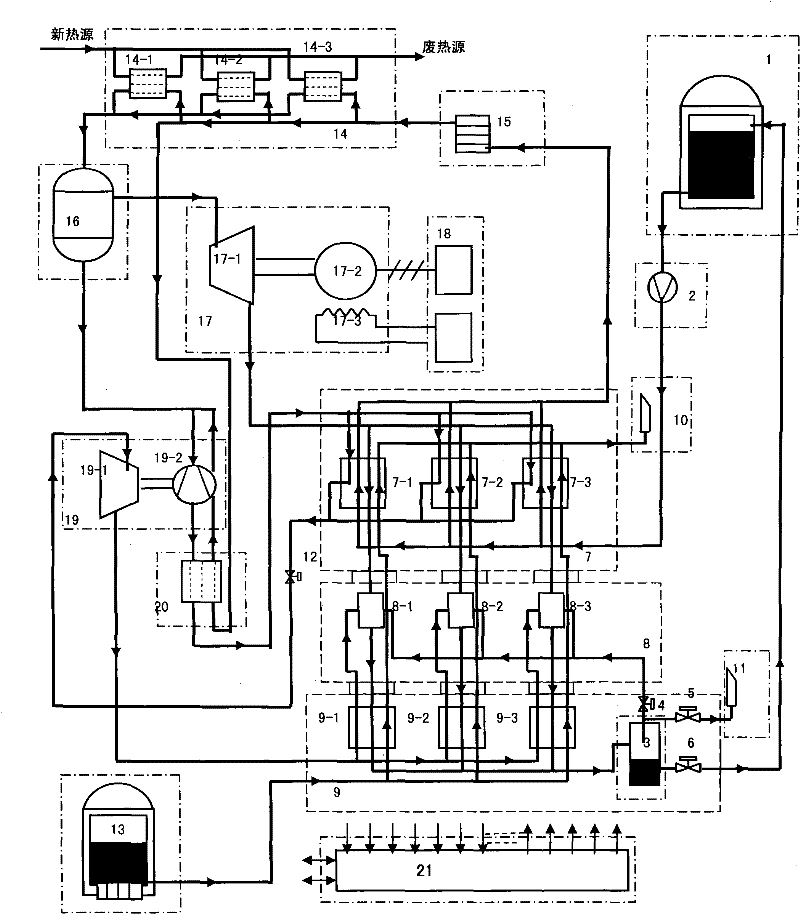
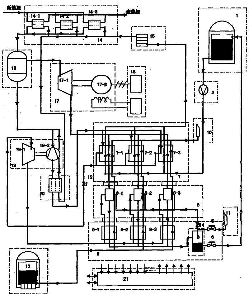
[0031] The cryogenic liquid pump 2 is pumped out from the vacuum insulation refrigerant storage tank 1, and the refrigerant is increased to a certain pressure (medium and high pressure) and kept stable, and then sent to the plate heat exchanger 7 through the vacuum insulation tube. It exchanges heat with the positive flow air from the turbo expander 17-1, completes the phase change and fully gasifies, enters the air bath heat exchanger 15 at an intercooling temperature slightly lower than the positive flow air, and sends it into the air bath heat exchanger after the temperature rises further. The air-water (or air-gas, gas-vapor) heat exchanger 14 fully exchanges heat with the heat source, and has a certain degree of superheat, and sends it into the buffer tank 16 after approaching the heat source inlet temperature. The gas coming out from the buffer tank is divided into two ro...


PUM


Abstract

Low-temperature thermal power generation is realized in a new circulating mode. Natural substances such as liquid air, liquid nitrogen, liquid argon (1) and the like which exist in the atmosphere are taken as refrigeration working substances; the liquid nitrogen and the liquid argon are taken as assistant cold sources (13); the working substances are conveyed by a low-temperature liquid pump (2) in a pressure boosting mode; the working substances are cooled and cold is recovered by a low-temperature heat exchanging device (7); an intermediately-cold working substance performs heat exchange (15 and 14) with a low-grade heat source to generate intermediate-and-high pressure gas; one part of gas working substance of which the enthalpy value is increased is inflated to do work to generate electricity (17); and electric energy is merged into a local power grid (18). The other part of working substance is inflated in the pressure boosting mode (19) to generate the cold; the working substance is cooled, condensed, mixed and recovered by a low-temperature heat exchanging device (9) and an ejector (8); the working substance is supercooled in a liquefying mode (5) and recycled; and parameter detection, control and the like are realized by a computer control system (21).

Description

a technical field [0001] This technology involves technical fields such as power generation, refrigeration, thermal power, environmental protection, machinery manufacturing and automation. Two background technology [0002] Low-temperature heat energy (low-grade heat energy, low-quality heat energy) refers to low-level heat energy with a temperature below 120°C, including solar energy, geothermal energy, surface hydrothermal energy, surface and building radiant heat energy, and industrial waste heat energy. The total amount is huge and renewable. sex. Taking industrial waste heat as an example, about 50% of the heat energy is discharged in the form of low-grade waste heat, especially in the form of low-temperature hot water (more than one-third of the thermal efficiency of thermal power plants is lost in the condenser and taken away by circulating cooling water, When the gas is isothermally compressed, the heat energy taken away by the cooling water is equivalent to the wor...

Claims


Application Information

Patent Timeline
IPC IPC(8): F01K27/00F01K25/10F01D15/10F25J3/00
Inventor 墙新奇
Owner 墙新奇
Learn More