Rotary compressor

A technology of rotary compressor and compression mechanism, applied in the direction of rotary piston machinery, rotary piston pump, mechanical equipment, etc., can solve the problems of bearing rigidity decrease, compression cavity deformation, reliability decrease, etc. The effect of improving strength and improving reliability

Inactive Publication Date: 2011-11-09
GUANGDONG MEIZHI COMPRESSOR
View PDF5 Cites 18 Cited by
  • Summary
  • Abstract
  • Description
  • Claims
  • Application Information

AI Technical Summary

Problems solved by technology

On the other hand, the bearings of conventional rotary compressors equipped with reed-type discharge valves have large discharge valve housing grooves and thin bottom surfaces, resulting in a decrease in the rigidity of the bearings.
As a result, the deformation of the compression chamber increases and this increase leads to loss of efficiency and deformation of the bearing, which reduces reliability

Method used


Image

  • Rotary compressor
  • Rotary compressor
  • Rotary compressor

Examples


Embodiment 1

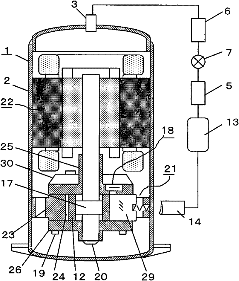
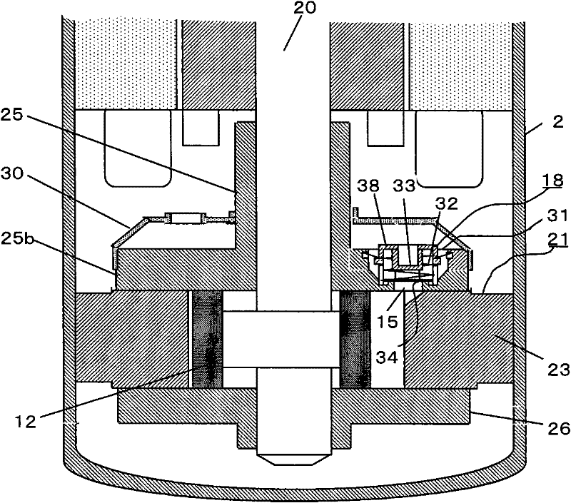
[0048] see figure 1 , the rotary compressor 1 is composed of a compression mechanism part 21 installed in the sealed casing 2 and a motor part 22 arranged on the top thereof. The compression mechanism part 21 is supported by a cylinder 23, a piston 12 that rotates eccentrically in the cylinder compression chamber 24, a sliding plate 29 that reciprocates synchronously with the piston 12, and a crankshaft 20 that drives the piston 12 through an eccentric shaft 17 arranged on it. The main bearing 25 and the sub bearing 26 of the crankshaft 20 are comprised. On the upper part of the main bearing 25, the discharge muffler 30 which was press-processed is arrange|positioned. The above components are connected and assembled with screws 19 to complete the compression mechanism unit 21 . The assembled compression mechanism part 21 and motor part 22 are fixed in the sealed case 2 , and then a head is welded to the sealed case 2 to complete the rotary compressor 1 .

[0049] In a refri...

Embodiment 2

[0082] In Example 1, the press-worked discharge muffler 30 is attached to the upper part of the main bearing flat part 25b. Figure 15-Figure 17 In the illustrated second embodiment, the discharge valve device is accommodated in the silencer chamber instead of the discharge silencer 30 by providing the silencer chamber 51 inside the main bearing flat portion 25b of the sealed main bearing 27 in advance. As a result, the rigidity and sound-proof effect of the sealed main bearing 27 can be improved; and, as will be described later, the sound-absorbing chamber 51 can be completely sealed.

[0083]The assembly groove in this embodiment is the second assembly groove 55, and the discharge valve plate is the second discharge valve plate 58 with a cutout 59, the second assembly groove 55 communicates with the silencer cavity 51, and the upper and lower mechanisms in the discharge valve device include a sealing cover 57, the sealing cover is fixed in the muffler cavity 51, an air passa...

Embodiment 3

[0095] As mentioned above, the embodiment of the silencer chamber 51 formed integrally by the sealed main bearing 27 through casting has been described; however, the sealed main bearing 27 can also be realized through a technical solution in which two components are connected, that is, the first zero After part 61a and second part 61b are connected, also can obtain and the equivalent effect of above-mentioned technical scheme, see Figure 19 . In this case, the two parts are connected, for example, by copper brazing or laser welding. Comparing this technical solution with the one-piece casting solution related to castings, it can be concluded that the technical solution for the connection of two parts has the disadvantages of increasing the number of welding points of the parts and the amount of connection work, but it does not require the core necessary for the casting method And the advantages of easy machining. The number of connection points of two parts is not limited t...


PUM


Abstract

The invention discloses a rotary compressor. In the rotary compressor, a motor part and a compression mechanism part are arranged in a seal shell; and the compression mechanism part comprises cylinders, a piston which is eccentrically rotated in a cylinder compression cavity, a crankshaft which is rotated to drive the piston, a main bearing and an auxiliary bearing which are used for supporting the crankshaft and sealing the cylinder compression cavity, and a slip sheet of which the tip end is connected with the periphery of the piston. The rotary compressor is characterized in that: a discharge valve device is arranged on the main bearing and/or the auxiliary bearing and comprises assembly grooves, a discharge hole, a valve seat which are arranged on the main bearing and/or the auxiliary bearing, discharge valve plates which move up and down on the valve seat and are used for opening and closing the discharge hole, an up-and-down mechanism which is used for limiting the up-and-down operation ranges of the discharge valve plates, and a horizontal mechanism which is positioned on the outer side of the valve seat and is used for limiting the horizontal operation ranges of the discharge valve plates; one end of the discharge hole is communicated with the assembly grooves, and the other end of the discharge hole is communicated with the cylinder compression cavity; and the valve seat is arranged on the outer side of the discharge hole. The rotary compressor has the characteristics of high bearing intensity, low operation noise and high compression efficiency.

Description

technical field [0001] The present invention relates to a rotary compressor. Background technique [0002] Systems equipped with rotary compressors are popular all over the world. To improve the efficiency of the system, the most important thing is to improve the compressor and improve its reliability. On the other hand, conventional rotary compressors have used reed type discharge valves for a long time. On the other hand, the bearing of a conventional rotary compressor equipped with a reed type discharge valve has a large discharge valve receiving groove and a thin bottom surface, so the rigidity of the bearing is reduced. As a result, the deformation of the compression chamber increases and this increase leads to loss of efficiency and deformation of the bearing, thereby reducing reliability. [0003] Patent Document 1: Patent publication Heisei 04-081582 The discharge valve device of the rotary compressor, [0004] Patent Document 2: Patent Publication Heisei 04-03609...

Claims


Application Information

Patent Timeline
Patent Type & Authority Applications(China)
IPC IPC(8): F04C18/344F04C29/12
Inventor 小津政雄李华明
Owner GUANGDONG MEIZHI COMPRESSOR
Why Eureka
Try Eureka