Compact efficient modularized oil flushing device

An oil flushing, modular technology, applied in chemical instruments and methods, cleaning methods and utensils, cleaning methods using liquids, etc., can solve the problems of large size of the flushing station, waste of materials and man-hours, and on-site arrangement of the flushing station, etc. To achieve the effect of convenient on-site layout and transportation, reducing measures and materials, and saving oil flushing time

Active Publication Date: 2013-08-21
TIANJIN 20 CONSTR
View PDF5 Cites 1 Cited by
  • Summary
  • Abstract
  • Description
  • Claims
  • Application Information

AI Technical Summary

Problems solved by technology

This leads to the situation that when the oil is flushed, sometimes the inspection is qualified on the first day and the inspection is not qualified on the second day
[0006] 2. At the same time, due to the pipe diameter and pipe length of the hydraulic system, different flushing flow rates are required, ranging from 1000L / min to 3000L / min. Therefore, oil flushing devices with different flow rates must be produced; at the same time, the flushing station needs to be transported frequently to different On the construction site, due to the large size of the washing station, it is difficult to arrange the washing station and transport it on site
At present, the purging is carried out one by one on site, and the pipe joints need to be disassembled one by one, which is time-consuming and laborious
[0008] 4. The connection of oil flushing adopts temporary pipeline connection. The technical requirements of temporary pipeline installation are the same as those of formal pipeline. After pickling, argon arc welding is required, and materials and man-hours are wasted
[0009] 5. The current washing station adopts single-stage filtration or two-stage filtration, and the filtration time is long

Method used


Image

  • Compact efficient modularized oil flushing device
  • Compact efficient modularized oil flushing device
  • Compact efficient modularized oil flushing device

Examples


Embodiment Construction

[0036] The compact and high-efficiency modularized oil flushing device of the present invention will be described in detail below in conjunction with the embodiments and accompanying drawings.

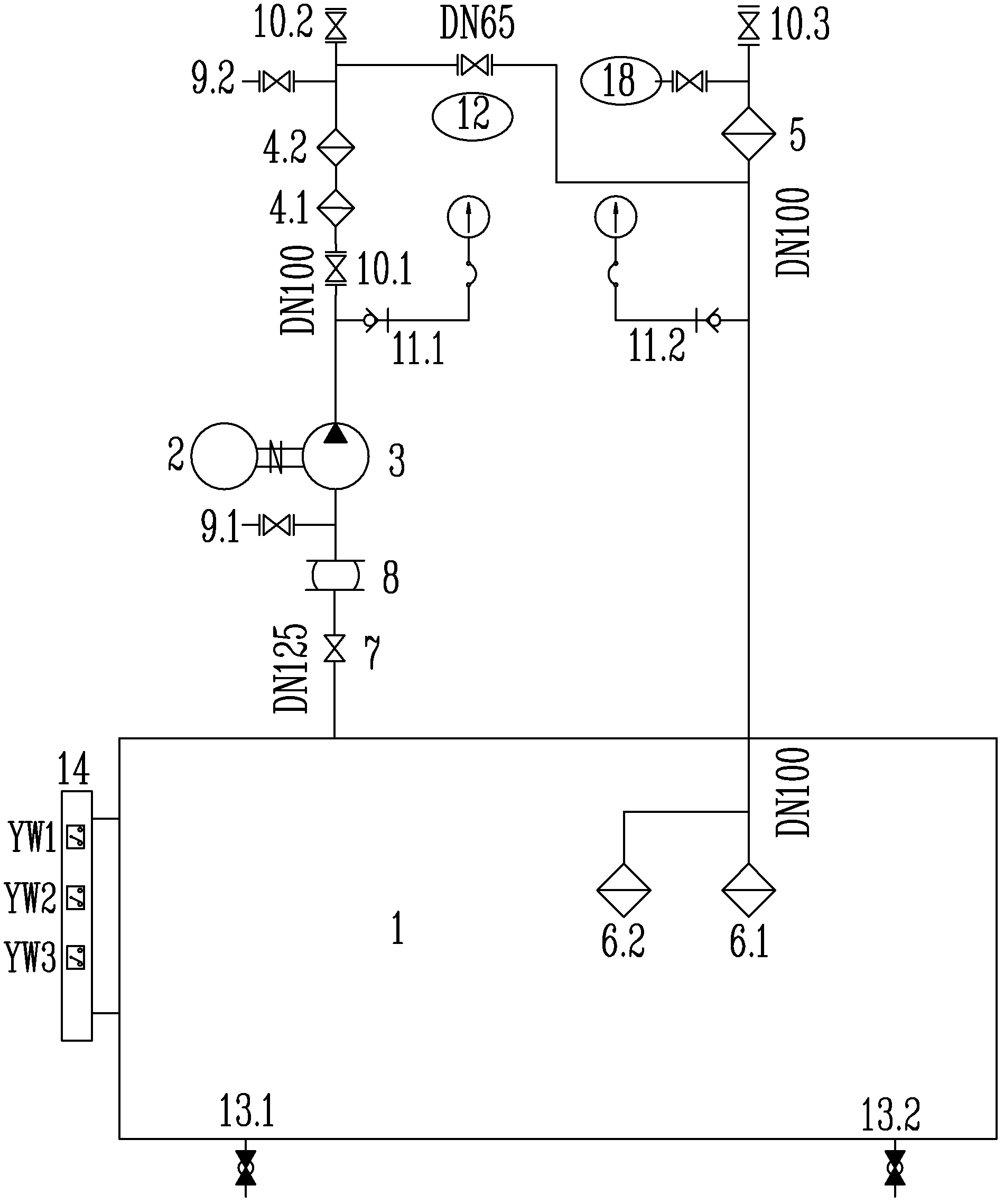
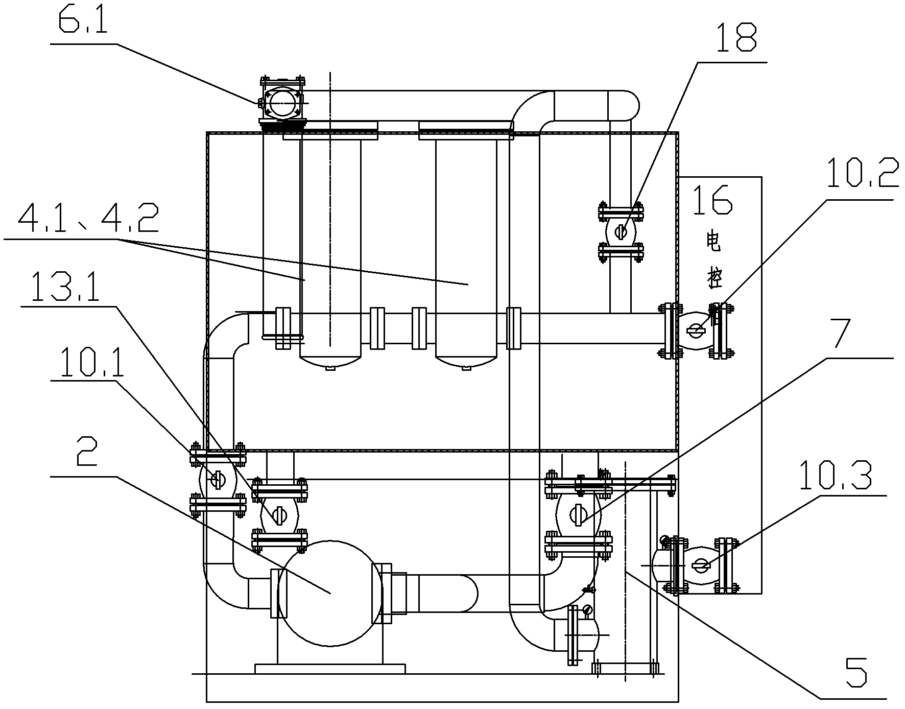
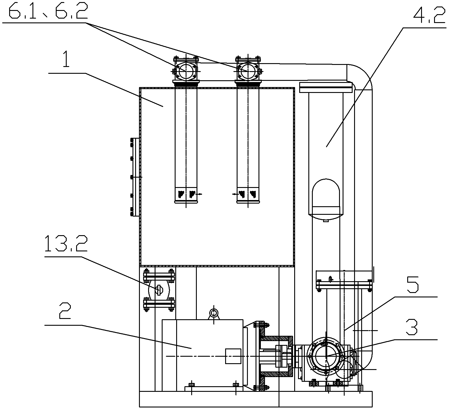
[0037] Such as Figure 1 to Figure 4 As shown, the compact and high-efficiency modularized oil flushing device of the present invention includes: an oil tank 1, the oil outlet of the oil tank 1 passes through the first ball valve 7 connected by the pipeline, the rubber joint 8, the first side ball valve 9.1, The helical gear pump 3 driven by the motor 2, the second ball valve 10.1, the first filter 4.1, the second filter 4.2, the second side ball valve 9.2 and the third ball valve 10.2 are connected to the oil outlet of the oil flushing device. The oil return port of the oil tank 1 passes through the low-pressure oil return filter 5, the third side ball valve 18 and the fourth ball valve 10.3 connected by the pipeline to the oil return port of the oil flushing device in sequence, and t...


PUM


Abstract

A compact efficient modularized oil flushing device is disclosed. The oil outlet tank is communicated with the oil outlet of the oil flushing device orderly through a first ball valve, a rubber adapter, a first side ball valve, a bevel gear pump driven by a motor, a second ball valve, a first filter, a second filter, a second side ball valve and a third ball valve which are communicated with eachother through pipelines. The oil return opening of the oil tank is communicated with the oil return opening of the oil flushing device orderly through a low-pressure oil return filter, a third side ball valve and a fourth ball valve which are communicated with each other through pipelines. The oil inlet side of the third ball valve is further communicated with the oil outlet side of the low-pressure oil return filter through a pipeline on which a fifth ball valve is arranged. Two overhead oil return filters both communicated with the oil inlet are further arranged on the oil tank. Besides, the motor and the bevel gear pump both are arranged under the outer side of the oil tank. The flushing station of the compact efficient modularized oil flushing device is high in number of filtering stages and high in flushing speed; full circulation of the flushing oil can be realized; all the components are be modularly combined to realize modularized production of a flushing system; the volume and the weight of the device are low; and the oil flushing time is saved and the oil flushing efficiency thereby is improved.

Description

technical field [0001] The invention relates to an oil flushing device. In particular, it relates to a compact and high-efficiency modularized oil flushing device which saves oil flushing time and improves oil flushing efficiency by installing the oil pump motor under the oil tank. Background technique [0002] At present, the general oil flushing device in China has the following status quo: [0003] 1. At present, the design of domestic oil flushing devices adopts that the base of the oil pump motor and the base of the oil tank are at the same level. The suction inlet of the oil pump is higher than the bottom of the oil tank. In order to ensure that the oil pump does not pump air, it is generally required that the minimum liquid level of the oil tank is 75mm higher than the pump inlet or 1.5 times the pipe diameter, whichever is greater. Such a design is feasible for the workstation in the production workshop, but for the oil flushing device, there are the following defe...

Claims


Application Information

Patent Timeline
Patent Type & Authority Patents(China)
IPC IPC(8): B08B3/04
Inventor 杜军科卞广雪李广权张玉红李国玉黄振春
Owner TIANJIN 20 CONSTR
Why Eureka
Try Eureka