Double-cutterhead horizontal ultra-precision hydrostatic motorized spindle system

An ultra-precision, double-cutter technology, applied in fine working devices, working accessories, stone processing equipment, etc., can solve the problems of low rigidity and low processing efficiency, and achieve high transmission efficiency, improved processing efficiency, and good dynamic effect. Effect

Active Publication Date: 2011-11-16
HARBIN INST OF TECH
View PDF4 Cites 3 Cited by
  • Summary
  • Abstract
  • Description
  • Claims
  • Application Information

AI Technical Summary

Problems solved by technology

[0003] In order to solve the problems of low rigidity and low processing efficiency of the spindle system of the existing KDP ultra-precision machining machine tool, the present invention further provides a double-cutter horizontal ultra-precision hydrostatic spindle system

Method used


Image

  • Double-cutterhead horizontal ultra-precision hydrostatic motorized spindle system
  • Double-cutterhead horizontal ultra-precision hydrostatic motorized spindle system
  • Double-cutterhead horizontal ultra-precision hydrostatic motorized spindle system

Examples


specific Embodiment approach 1

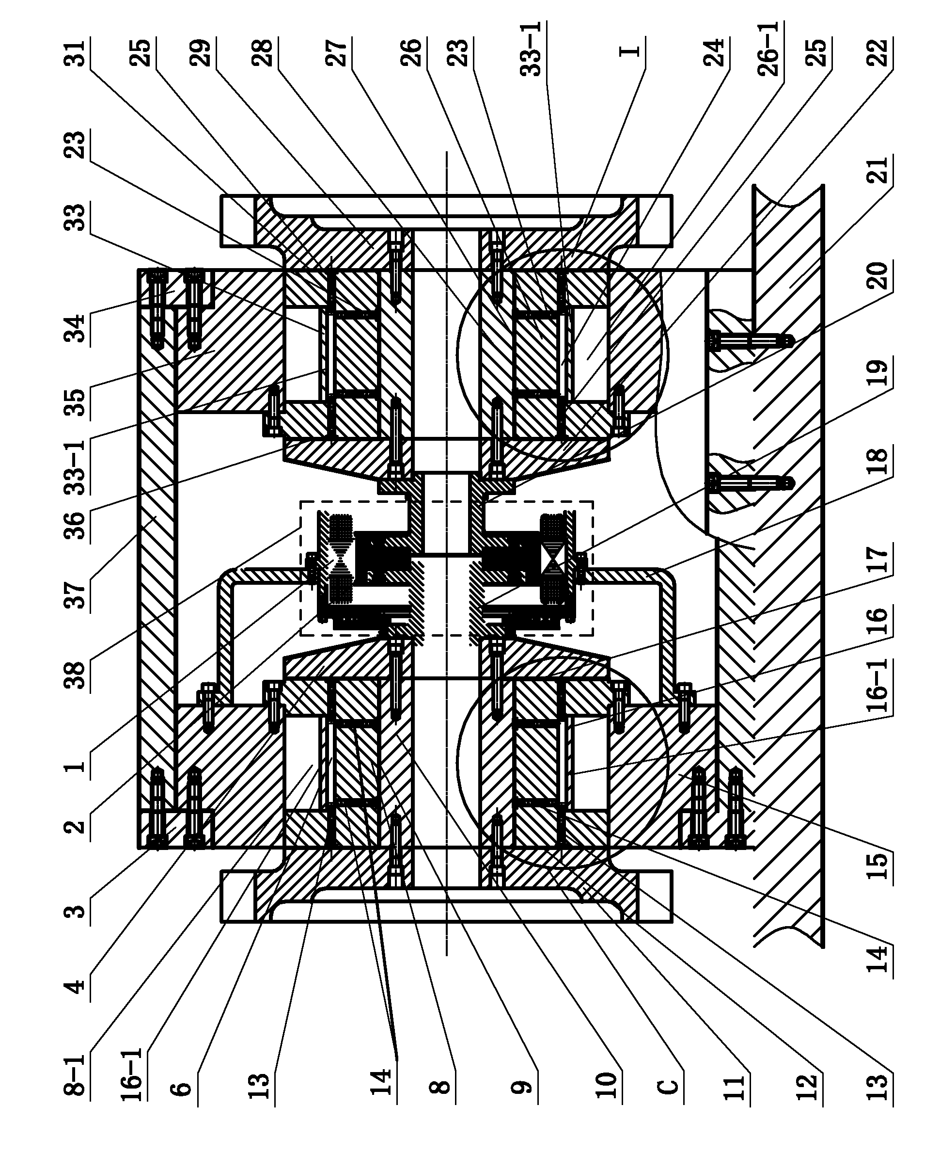
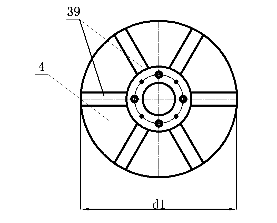
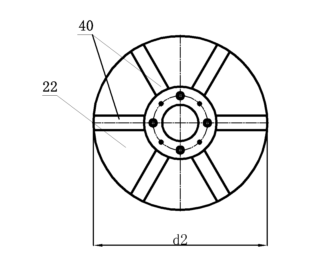
[0010] Specific implementation mode one: as Figure 1-7 As shown, the double cutterhead horizontal ultra-precision hydrostatic electric spindle system of this embodiment includes a first fixed baffle 3, a first spindle 10, a motor bracket 18, a first thrust plate 4, a first cutterhead 11, The first shaft sleeve 8, the first shafting bracket 15, the first oil chamber cover 16, the housing 37 and the DC double output shaft motor 38, the main shaft system also includes the second fixed baffle 34, the second main shaft 28, the first Two thrust plates 22, a second cutter head 29, a second shaft sleeve 26, a second oil chamber cover 33 and a second shafting bracket 35; the first shafting bracket 15 is located at one end of the inner cavity of the casing 37, so that The first shafting bracket 15 is fixedly connected to the housing 37 through the first fixed baffle 3, the second shafting bracket 35 is located at the other end of the inner cavity of the housing 37, and the second shaft...

specific Embodiment approach 2

[0013] Specific implementation mode two: as figure 1 As shown, the DC dual output shaft motor 38 in this embodiment is a DC dual output shaft brushless drive motor. With such a design, the driving effect is good. Other components and connections are the same as those in the first embodiment.

[0014] The DC dual output shaft motor 38 of the present embodiment is composed of a stator 1 and a rotor 2, and the rotor 2 of the DC brushless drive motor system 38 is fixedly connected with the first motor shaft 19 and the second motor shaft 20 at the same time, and the brushless drive motor is used as The driving element, since there is no brush, there is no frictional moment between the stator 1 and the rotor 2 of this motor, and the rotational torque can be directly generated to drive the first main shaft 10 and the second main shaft 28 to rotate simultaneously and perform cutting.

specific Embodiment approach 3

[0015] Specific implementation mode three: as Figure 4 As shown, the ranges of the first gap D, the second gap E, and the third gap F in this embodiment are all 4-6 μm. Such a design effectively improves the rigidity of the hydrostatic oil film and realizes the ultra-precise rotation of the first main shaft 10 . Other compositions and connections are the same as those in Embodiment 1 or 2.


PUM


Abstract

The invention discloses a double-cutterhead horizontal ultra-precision hydrostatic motorized spindle system and relates to a hydrostatic motorized spindle system. The invention aims at solving the problems of low rigidity and low machining efficiency of a spindle system of the existing KDP (potassium dihydrogen phosphate) ultra-precision machining tool. A first shaft system support is positioned at one end of an inner cavity of a housing, the first shaft system support is fixedly connected with the housing through a first fixed baffle plate, a second shaft system support is positioned at the other end of the inner cavity of the housing, a first output shaft of a direct current double-output shaft motor is fixedly connected with one end of a first spindle through a first thrust plate, the other end of the first spindle is fixedly connected with a first cutterhead, a first spindle sleeve is sheathed on the first spindle, and the first spindle sleeve is fixedly arranged on the first shaft system support; and a second output shaft of the direct current double-output shaft motor is fixedly connected with one end of a second spindle through a second thrust plate, the other end of the second spindle is fixedly connected with a second cutterhead, a second spindle sleeve is sheathed on the second spindle, and the second spindle sleeve is fixedly arranged on the second shaft system support. The spindle system is used for machining KDP crystal optical parts.

Description

technical field [0001] The invention relates to a hydrostatic electric spindle system, in particular to a double-cutter horizontal ultra-precision hydrostatic electric spindle system. Background technique [0002] Driven by the technological demands of laser nuclear fusion and strong laser weapons, many countries have successively built multiple large-scale laser devices, requiring a large number of optical components. KDP crystals are widely used due to their high nonlinearity and laser damage threshold. Applied in the field of laser and nonlinear optics. KDP crystal optical parts require high-precision surface quality and good surface roughness, but KDP crystals are soft and fragile, which are not conducive to optical processing. Traditional grinding and polishing methods are not suitable for processing KDP crystals. Ultra-precision machining technology must be used to process KDP crystals. The processing of KDP crystals must use special KDP ultra-precision machining mach...

Claims


Application Information

Patent Timeline
Patent Type & Authority Applications(China)
IPC IPC(8): B28D7/00B28D5/00
Inventor 梁迎春张飞虎孙雅洲刘海涛
Owner HARBIN INST OF TECH
Why Eureka
Try Eureka