Lamp radiator structure

A technology of structure and lamps, which is applied to cooling/heating devices of lighting devices, lighting and heating equipment, parts of lighting devices, etc. It can solve the problems of different diameters, increased resistance, waste of cold air, etc., and achieve heat load Uniform distribution, reduced airflow resistance, good heat dissipation effect

Inactive Publication Date: 2011-11-16
PR LIGHTING
View PDF4 Cites 15 Cited by
  • Summary
  • Abstract
  • Description
  • Claims
  • Application Information

AI Technical Summary

Problems solved by technology

[0005] First of all, the cooling disc of this invention is generally parallel to the opening plane of the reflective bowl, and the lamp tube of this invention is installed along the axis of the reflective bowl. It has only one end fixed on the lamp holder, and the other end is suspended in the reflective bowl. In the light path; the cooling air flow is from the inside of the reflective bowl through the round hole at the bottom of the reflective bowl and then back to the back of the reflective bowl. The clamping portion of the tube electrode is surrounded by high-temperature air flow, and the invention uses a manifold to introduce cold air to drive away the hot air (making surge), so that a part of cold air is wasted; and when the cooling air flow passes through the reflective bowl from the inside of the reflective bowl When the round hole at the bottom turns back to the back of the reflective bowl, the flow direction changes sharply, and the resistance increases. As a result, the closer the cooling disc is to the height of the reflective bowl mouth, the less the flow between the discs, and the heat load on the disc is uneven.
[0006] Secondly, the center of each disc should keep a certain distance from the back of the reflective bowl. Because the reflective bowl is in the shape of a parabola, the diameter of the hole in the middle of each disc is different, so it is necessary to equip multiple molds for processing a set of discs. Case
[0007] The pipe of this invention is a round pipe, and its cross-sectional area is smaller than a square whose side is its diameter. A lot of space will be wasted when the round pipe is laid in the lamp, and the process of changing the diameter and bending of the pipe is more complicated.

Method used


Image

  • Lamp radiator structure
  • Lamp radiator structure
  • Lamp radiator structure

Examples


Embodiment Construction

[0020] The present invention will be described in further detail below in conjunction with the accompanying drawings and embodiments.

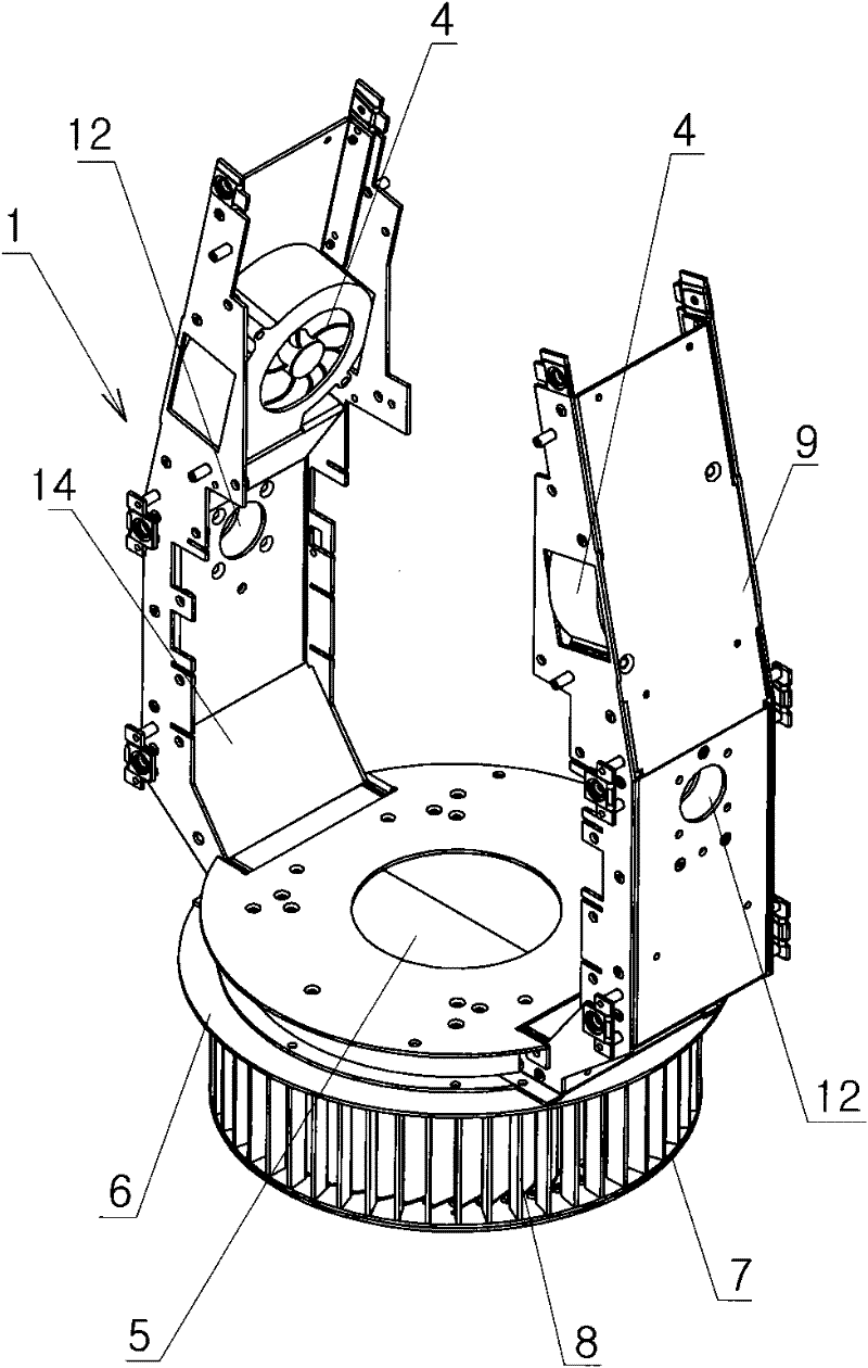
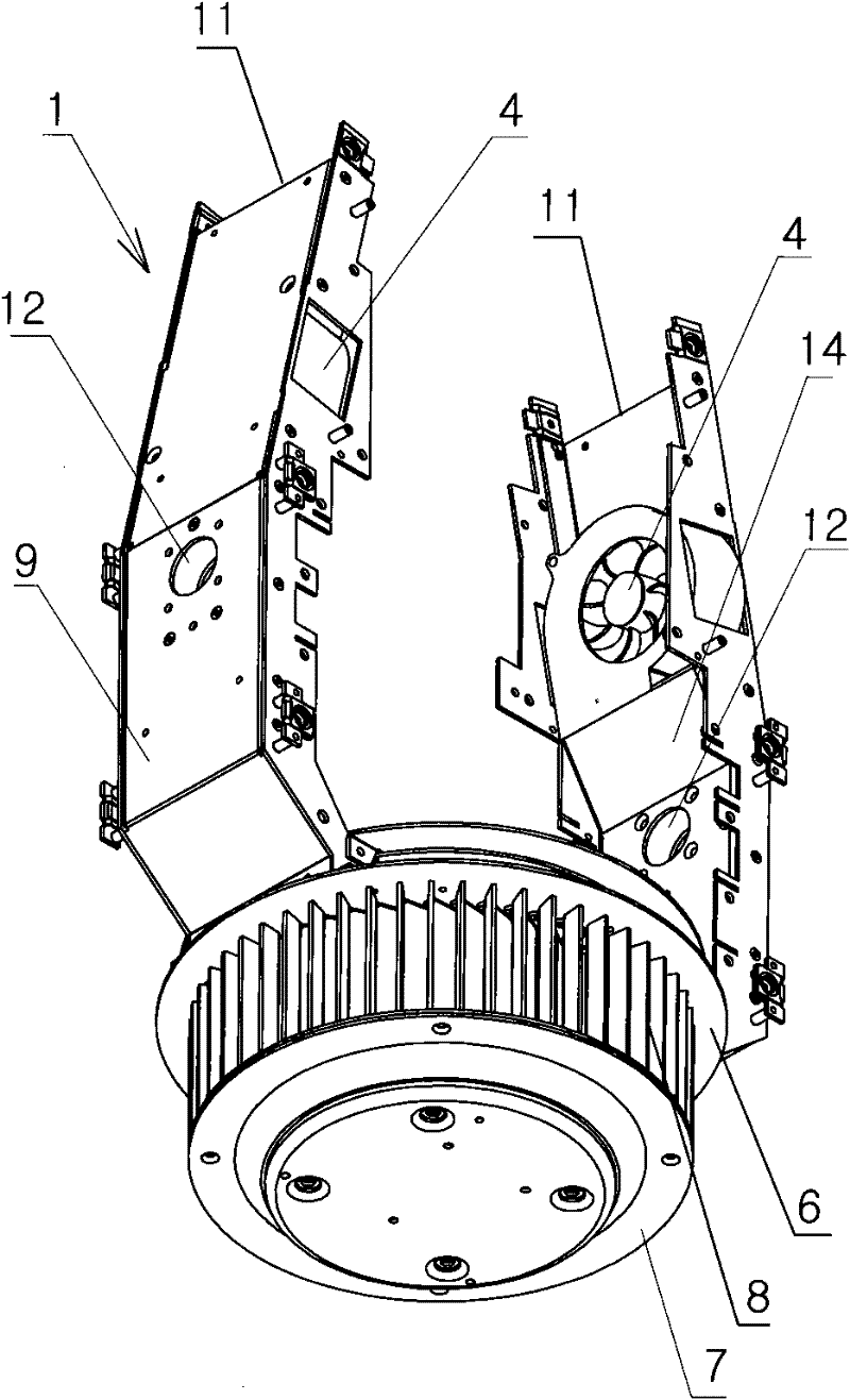
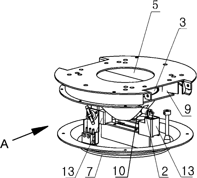
[0021] see Figure 1 to Figure 4 , this embodiment is a moving head light, which has a main body frame 1 made of metal plates, the left and right arms 11 of the main body frame 1 are used to install modules such as focusing, dimming, and color mixing. The base (not shown) is hinged, and the housing (not shown) of the lamp is also mounted on the two arms.

[0022] The radiator is connected below the main frame 1; the radiator is cage-shaped and consists of an upper ring 6, a chassis 7 and fifty fins 8, and one end of each fin 8 along its axis is fixed on the upper ring 6, The other end of each fin 8 along its axis is fixed on the chassis 7, and fifty fins 8 are evenly distributed and installed upright along the upper ring 6 and the circumference of the chassis 7, with air gaps between adjacent fins 8 . The fins 8 can be arc-shaped or straight...


PUM


Abstract

The invention discloses a lamp radiator structure and belongs to lamps. The lamp radiator structure comprises a main body frame, a bulb, a reflective bowl, a fan, a heat insulation transparent plate and a radiator, and is characterized in that: the radiator has a cage shape, is enclosed outside a bulb and consists of an upper ring, a chassis, a plurality of fins and one or more closed air guide cavities attached to the main body frame, wherein one end of each fin along an axis is fixed on the circumference of the upper ring and the other end of each fin along the axis is fixed on the circumference of the chassis; an air gap is formed between adjacent fins; partial cavity walls of the air guide cavities consist of the main body frame; the air guide cavities approximately extend from top to bottom along an inner wall of the main body frame; an air outlet of the fan is communicated with a beginning end of the air guide cavities; and a tail end of the air guide cavities passes through a space enclosed by the reflective bowl and the heat insulation transparent plate. Airflow at the air outlet is radially dispersed, the airflow resistance is low, thermal load of the fins is uniform and the radiating effect is good; and the lamp radiator structure is suitable for lamps such as stage lamps, projection lamp and the like.

Description

technical field [0001] The present invention relates to lamps. Background technique [0002] The power of stage lamps is relatively large, especially lamps with gas discharge lamps or tungsten halogen lamps as light sources generally reach kilowatts or thousands of watts of power consumption, and generate a lot of heat when they work. The traditional heat dissipation structure uses a fan installed near the outer surface of the lamp to suck the external cold air into the lamp body, pass through the outside of the reflector, and force it out of the lamp. Because it is close to the heating element, the working environment temperature of the motor and the fan is high, which is easy to cause failure. At the same time, the high temperature also causes the lamp shell to partially melt and the screws to slip. [0003] Application No. 200810131481 Patent for Invention "Light source module for lighting equipment" discloses a method for generating air flow for cooling light sources an...

Claims


Application Information

Patent Timeline
Patent Type & Authority Applications(China)
IPC IPC(8): F21V29/02F21V17/00F21V29/67F21V29/77
Inventor 梁志威
Owner PR LIGHTING
Why Eureka
Try Eureka