Process and device for recycling flue gas afterheat of electric furnace

A flue gas waste heat and electric furnace technology, which is applied in the field of iron and steel metallurgy, can solve the problems of fast cooling speed, slow recovery of waste heat, large cooling water volume, etc., and achieve the effects of avoiding recombination, achieving standard discharge, and high heat exchange intensity

Active Publication Date: 2011-11-16
北京中冶设备研究设计总院有限公司
View PDF7 Cites 19 Cited by
  • Summary
  • Abstract
  • Description
  • Claims
  • Application Information

AI Technical Summary

Problems solved by technology

This method of utilizing waste heat from electric furnace flue gas has the following defects: 1. Water cooling method is adopted, and the amount of cooling water is large, which consumes a large amount of electric energy; 2. The method of spray cooling is adopted, and the cooling speed is fast. The problem of evil, but it causes a lot of waste heat to be unusable. At the same time, it increases the flow of flue gas and increases the po...

Method used


Image

  • Process and device for recycling flue gas afterheat of electric furnace
  • Process and device for recycling flue gas afterheat of electric furnace
  • Process and device for recycling flue gas afterheat of electric furnace

Examples


Embodiment Construction

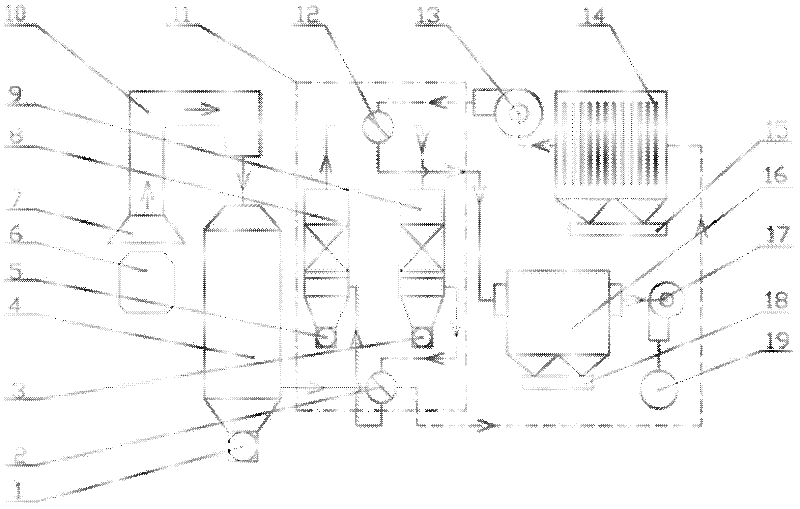
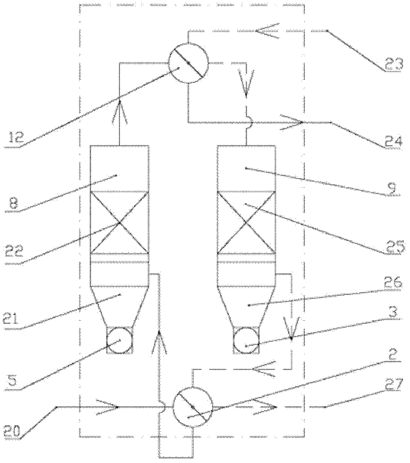
[0010] The embodiments of the present invention will be further described in detail below in conjunction with the accompanying drawings: a process for recovering and utilizing waste heat from electric furnace flue gas: figure 1 Shown: the high-temperature flue gas that electric furnace 6 produces, first passes fume cover 7, vaporization cooling flue 10, enters combustion settling chamber 4, and the harmful substances such as combustible gas and dioxin in the flue gas are fully burned and decomposed here. The flue gas with a temperature of 850-1000°C coming out of the combustion settling chamber 4 enters the regenerative rapid cooling device 11, which is composed of two sets of heat exchange units A8 and B9. After the heat is transferred to the circulating air, the temperature drops below 150°C, and then the flue gas enters the high-efficiency bag filter 16 for fine dust removal, ensuring that the dust content of the flue gas coming out of the high-efficiency bag filter 16 is re...


PUM


Abstract

The invention provides a process for recycling flue gas afterheat of an electric furnace. The process comprises the following steps: firstly passing high-temperature flue gas generated by the electric furnace through a flue gas hood and an evaporative cooling flue so as to enter into a burning settling chamber, introducing the discharged flue gas into a heat accumulating type rapid cooling device, changing the working conditions of two heat accumulating units (A and B) of the heat accumulating type rapid cooling device periodically, introducing the flue gas into a bag-type dust collector for dedusting, and then discharging the processed flue gas into the atmosphere through a draft fan and a chimney. The invention provides a device for recycling flue gas afterheat of the electric furnace. The device mainly comprises the hood, a flue, the burning settling chamber, a flue gas inlet, a flue gas outlet, a circulating inlet, a circulating air outlet, a circulating fan, a convection type afterheat boiler, the bag-type dust collector, the draft fan and the chimney, and is characterized in that the heat accumulating type rapid cooling device is installed on the back of the burning settling chamber, mainly consists of a heat transfer unit A and a heat transfer unit B which are provided with honeycomb ceramic heat accumulators, and has two operating modes. The process and device for recycling the flue gas afterheat of the electric furnace have the advantages of realizing full recovery of low-temperature flue gas afterheat, simultaneously avoiding the new synthesis of dioxin, and realizing the standard flue gas emission.

Description

Technical field: [0001] The invention relates to the technical field of iron and steel metallurgy, in particular to an electric furnace flue gas waste heat recovery and utilization process and equipment in steelmaking production. Background technique: [0002] The existing waste heat utilization method of electric furnace flue gas is that the high temperature flue gas generated by the electric furnace enters the water-cooled flue through the exhaust hood, and the temperature is reduced to 350°C after being sprayed and cooled by the combustion settling chamber and the water-cooled flue, and then combined with the secondary flue gas After mixing, it enters the bag filter, and the purified flue gas is discharged into the atmosphere through the exhaust fan and chimney. This method of utilizing waste heat from electric furnace flue gas has the following defects: 1. Water cooling method is adopted, and the amount of cooling water is large, which consumes a large amount of electric...

Claims


Application Information

Patent Timeline
IPC IPC(8): F27D17/00
CPCY02P10/25
Inventor 张富信张杰
Owner 北京中冶设备研究设计总院有限公司
Why Eureka
Try Eureka