Ultrasonic composite electric resistance welding method for TC4 and 718 steel

A composite resistance and ultrasonic technology, which is applied in the field of ultrasonic composite resistance welding and ultrasonic composite resistance welding devices, can solve the problems of reduced joint performance and inclusion of welded joints, and achieves improved performance, reduced heat exposure, and reduced heat embrittlement. Effect

Inactive Publication Date: 2011-11-23
XIAN UNIV OF TECH
View PDF5 Cites 4 Cited by
  • Summary
  • Abstract
  • Description
  • Claims
  • Application Information

AI Technical Summary

Problems solved by technology

[0005] The purpose of the present invention is to provide an ultrasonic compound resistance welding method for TC4 and 718 steel, which solves the problems of reduced joint performance and inclusion of welded joints caused by intermetallic compounds that cannot be overcome in the prior art

Method used


Image

  • Ultrasonic composite electric resistance welding method for TC4 and 718 steel
  • Ultrasonic composite electric resistance welding method for TC4 and 718 steel

Examples


Embodiment 1

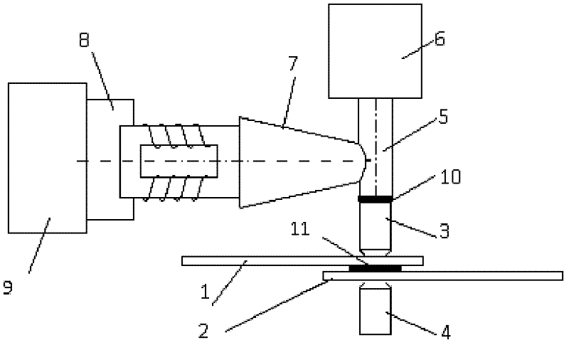
[0034] Set the working parameters of the ultrasonic generator 9: power P=80W, resonant frequency f=80kHz, amplitude A=0.1-5.0μm, duration t=120s; set the working parameters of the three-phase DC resistance welding machine: power W=120KW, welding Current I=18KA, welding pressure F=10KN, power-on time t=120s. By placing a V / Ni bimetal with a thickness of about 40-60 μm as an intermediate transition layer between the two weldments, the welding of the TC4 titanium alloy plate with a thickness of 2.0mm and the 718 steel plate is realized, and the shear strength of the joint reaches 381MPa.

Embodiment 2

[0036] Set the working parameters of the ultrasonic generator 9: power P=80W, resonant frequency f=100kHz, amplitude A=0.1-5.0μm, duration t=60s; set the working parameters of the three-phase DC resistance welding machine: power W=120KW, welding Current I=10KA, welding pressure F=15KN, power-on time t=180s. By placing a V / Ni bimetal with a thickness of about 40-60 μm as an intermediate transition layer between the two weldments, the welding of 3Cr2NiMo steel with a thickness of 2.0mm and Ti-6Al-4V titanium alloy is realized, and the shear strength of the joint is achieved. Up to 413MPa.

Embodiment 3

[0038] Set the working parameters of the ultrasonic generator 9: power P=80W, resonant frequency f=90kHz, amplitude A=0.1-5.0μm, duration t=40s; set the working parameters of the three-phase DC resistance welding machine: power W=120KW, welding Current I=8KA, welding pressure F=14KN, power-on time t=200s. By placing a V / Ni bimetal with a thickness of about 40-60 μm as an intermediate transition layer between the two weldments, the welding of the TC4 titanium alloy plate with a thickness of 1.5mm and the 718 steel plate is realized, and the shear strength of the joint reaches 403MPa.


PUM

PropertyMeasurementUnit
thicknessaaaaaaaaaa
thicknessaaaaaaaaaa
shear strengthaaaaaaaaaa

Abstract

The invention discloses an ultrasonic composite electric resistance welding method for TC4 and 718 steel. The ultrasonic composite electric resistance welding method for the TC4 and 718 steel particularly comprises the following steps of: 1) positioning the central part of a lap joint region of a TC4 titanium alloy plate, a metal intermediate transition layer and a 718 steel plate which are required to be welded on the axis of an upper electrode and a lower electrode of a three-phase direct current resistance welding machine; 2) intervening ultrasonic wave and pressurizing; and 3) performing welding operation, namely setting working parameters of an ultrasonic generator and the three-phase direct current resistance welding machine, applying welding pressure on the upper electrode, supplying power for the three-phase direct current resistance welding machine and the ultrasonic generator, switching on a circuit switch of the three-phase direct current resistance welding machine, starting to perform ultrasonic composite resistance welding on the TC4 titanium alloy plate and the 718 steel plate, and finishing the step after the set time is up. By the method, the problems of reduced joint performance and welding joint inclusion caused by intermetallic compounds which cannot be solved in the prior art are solved.

Description

technical field [0001] The invention belongs to the technical field of material preparation, and relates to an ultrasonic composite resistance welding device, and also relates to an ultrasonic composite resistance welding method using the device for TC4 and 718 steel. Background technique [0002] Titanium and its alloys have high specific strength and good corrosion resistance, and are important aerospace structural materials and chemical materials. However, due to the high price of titanium metal, titanium-steel dissimilar metal structures are commonly used in engineering, which can not only meet the performance requirements, but also save titanium materials. The key to manufacturing titanium-steel composite structures is to solve the welding problem of titanium and steel. [0003] The physical properties and crystallization chemical properties of titanium and steel are quite different, and a variety of brittle intermetallic compounds and carbides are easily formed in the...

Claims


Application Information

Patent Timeline
Patent Type & Authority Applications(China)
IPC IPC(8): B23K31/02
Inventor 翟秋亚徐锦锋陆天宇
Owner XIAN UNIV OF TECH
Why Eureka
Try Eureka