Printer feeding device

A technology of feeding device and printing machine, applied in printing machine, rotary printing machine, printing and other directions, can solve the problems of affecting the quality of printing process, unable to drive rubber roller, poor dust removal effect, etc., and achieve simple assembly, simplified structure, Easy-to-use effects

Inactive Publication Date: 2011-11-23
SUZHOU INDAL PARK TEAMS TECH
View PDF6 Cites 3 Cited by
  • Summary
  • Abstract
  • Description
  • Claims
  • Application Information

AI Technical Summary

Problems solved by technology

There is a problem with this dust removal device, that is, the contact surface between the paper and the rubber roller is small, and the friction force is too small, so it is often impossible to drive the rubber roller to rotate.
This leads to poor dust removal effect, and the paper after dust removal by the rubber roller will generate static electricity due to friction, which will affect the quality of the subsequent printing process

Method used


Image

  • Printer feeding device
  • Printer feeding device
  • Printer feeding device

Examples


Embodiment 1

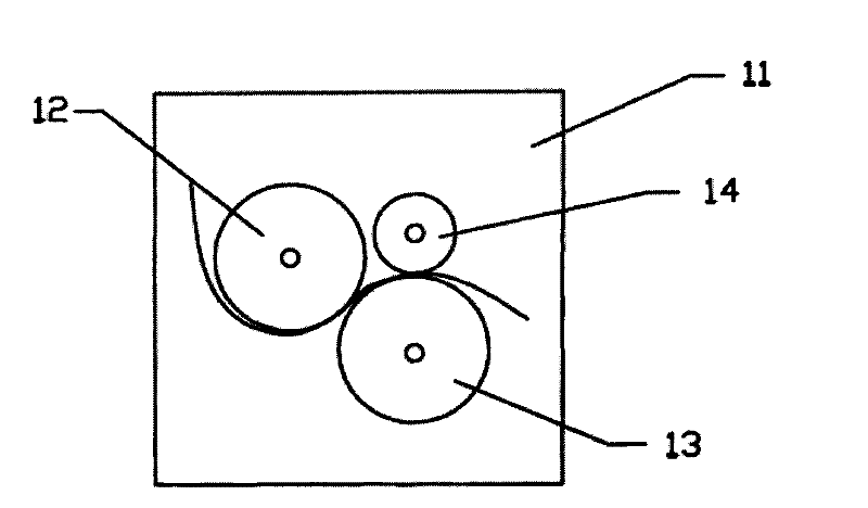
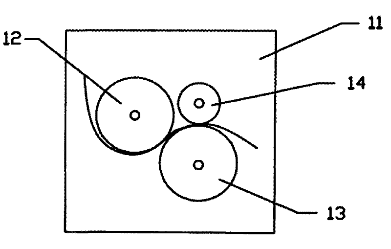
[0016] A kind of printing press feeding device of this embodiment, such as figure 1 Shown, comprise a gate-shaped frame 11, be provided with the last dust-sticking roller 12 and following dust-sticking roller 13 of axis distribution on two vertical planes parallel to each other in the gate-shaped frame 11, sticking dust roller 12 and following dust-sticking roller Roller 13 is sticky dust roller. Also be provided with a destaticizing roller 14 in the door-shaped frame 11, the axis between destaticizing roller 14 and following sticking dust roller 13 is parallel to each other, and is arranged on the same vertical plane; Last sticking dust roller 12, following sticking dust roller 13 and The static electricity removing rollers 14 can each rotate around the axis. The upper dust-sticking roller 12, the lower dust-sticking roller 13 and the static-removing roller 14 are all connected with a power device, and under the drive of the power device, the upper dust-sticking roller 12 an...

Embodiment 2

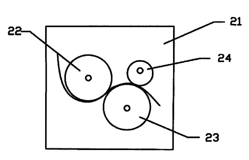
[0019] A kind of printing press feeding device of this embodiment, such as figure 2 Shown, comprise a door-shaped frame 21, be provided with the last dust-sticking roller 22 and the following dust-sticking roller 23 on the two vertical planes parallel to each other with the axes distributed in the door-shaped frame 21, the dust-sticking roller 22 and the following dust-sticking roller The roller 23 is a silica gel roller; a static removal roller 24 is also provided in the door frame 21, and the axes of the static removal roller 24 and the lower sticky dust roller 23 are distributed on two vertical planes parallel to each other; the upper sticky dust roller 22, the lower sticky roller Both the dust roller 23 and the static removal roller 24 can rotate around the axis respectively. The last dust sticking roller 22, the lower dust sticking roller 23 and the static removal roller 24 are all connected with a power device, and under the drive of the power device, the upper dust sti...


PUM


Abstract

The invention discloses a printer feeding device. The printer feeding device comprises a door-shaped frame, wherein an upper dust-sticking roller and a lower dust-sticking roller are arranged in the door-shaped frame, the axes of the upper and the lower dust-sticking rollers are distributed on two parallel vertical planes; a static-removing roller is further arranged in the door-shaped frame; thestatic-removing roller is parallel to the axis of the lower dust-sticking roller; and the upper dust-sticking roller, the lower dust-sticking roller and the static-removing roller all can rotate around the axes. In the invention, the dust-sticking rollers can quickly remove fine particles, impurities, dusts and the like on the surface of paper; the static-removing roller can effectively eliminatethe static generated during the dust removing process of the paper, and cooperates with the lower dust-sticking roller to play a role of stretching, so that paper does not cockle after the dust removal; the finished product ratio of printing products is improved; downtime for cleaning equipment is shortened; defective percentage and paper waste are reduced; the structure is simple; and the deviceis convenient to use.

Description

technical field [0001] The invention relates to the field of printing machinery, in particular to a feeding device of a printing machine. Background technique [0002] The printing machine is an important printing equipment. The creases of the paper when feeding, the dust and impurities attached to the surface of the paper will affect the printing quality of the final product, and the product will be scrapped in severe cases. In the printing process, in order to improve the printing quality, it is usually necessary to dedust the printed paper before printing. At present, a dust removal device that is often used is composed of a door-shaped frame. In the door-shaped frame, an upper dust-sticking roller, an upper rubber roller, a lower rubber roller and a lower dust-sticking roller are sequentially arranged from top to bottom. The axes among the upper dust-sticking roller, the upper rubber roller, the lower rubber roller and the lower dust-sticking roller are parallel to each...

Claims


Application Information

Patent Timeline
Patent Type & Authority Applications(China)
IPC IPC(8): B41F13/02
Inventor 钱洪海
Owner SUZHOU INDAL PARK TEAMS TECH
Why Eureka
Try Eureka