Eureka AIR delivers breakthrough ideas for toughest innovation challenges, trusted by R&D personnel around the world.

Air sampling aircraft and air sampling method

An air sampling and aircraft technology, applied in aircraft, sampling devices, motor vehicles, etc., can solve the problems of high energy consumption that cannot meet the high energy consumption of ordinary aircraft models, the flight time cannot exceed 15 minutes, and the conversion efficiency of solar panels is low. Mobility and propulsion, accurate and reliable sampling data, simple and reliable structure

Inactive Publication Date: 2011-11-23
杨当立
View PDF7 Cites 19 Cited by
  • Summary
  • Abstract
  • Description
  • Claims
  • Application Information

AI Technical Summary

Problems solved by technology

[0004] (1) Air sampling has very strict requirements on the surrounding wind speed. Generally, the wind speed needs to be lower than level 3. If the wind speed is too fast, it will affect the sampling, and the data obtained after sampling and analysis will lose its accuracy.
Therefore, fixed-wing aircraft models that cannot hover or fly at low speeds cannot meet the requirements, and the rotor aircraft has strong airflow around it, so it cannot be used for the research of this project.
[0005] (2) At present, the flight of aircraft models requires strong electric energy to provide support. With commonly used aircraft model batteries as power sources, the flight time cannot exceed 15 minutes, and the conversion efficiency of solar panels is too low to meet the needs of ordinary aircraft models. High energy consumption, without high-tech materials such as carbon fiber, the use of batteries cannot meet the requirements of this project
The burning of kerosene will inevitably produce pollutants, such as sulfur oxides, and the sampling reagents that are extremely sensitive to pollutants will definitely react with the exhaust gas produced by kerosene combustion to form secondary pollution, so that the sampling work cannot be carried out

Method used


Image

  • Air sampling aircraft and air sampling method
  • Air sampling aircraft and air sampling method
  • Air sampling aircraft and air sampling method

Examples


Embodiment Construction

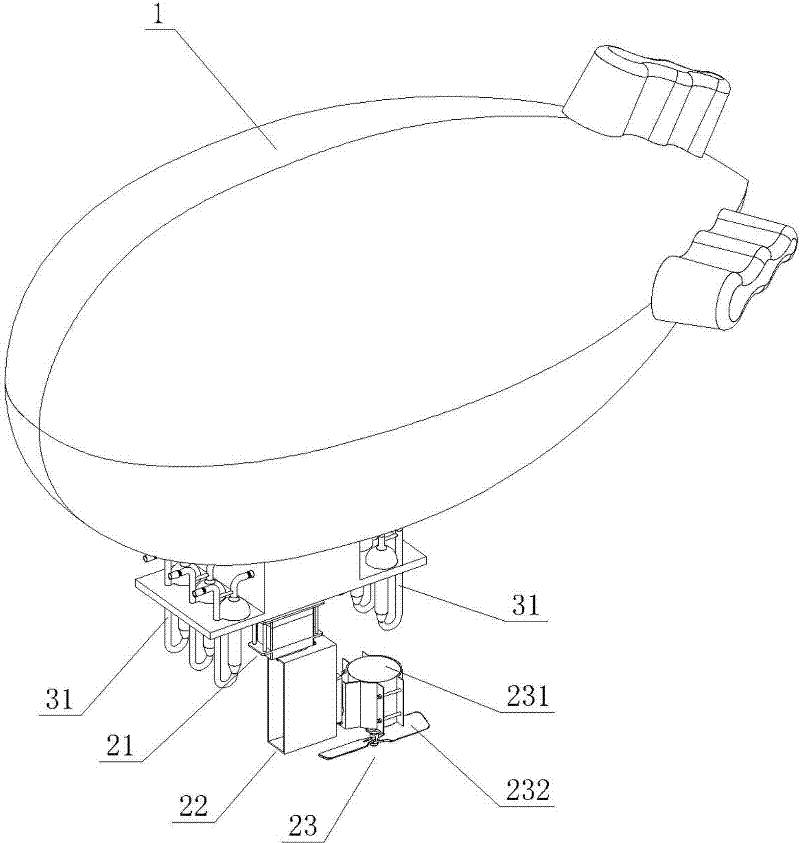
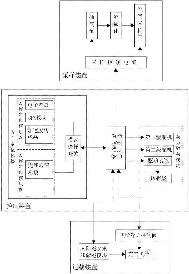
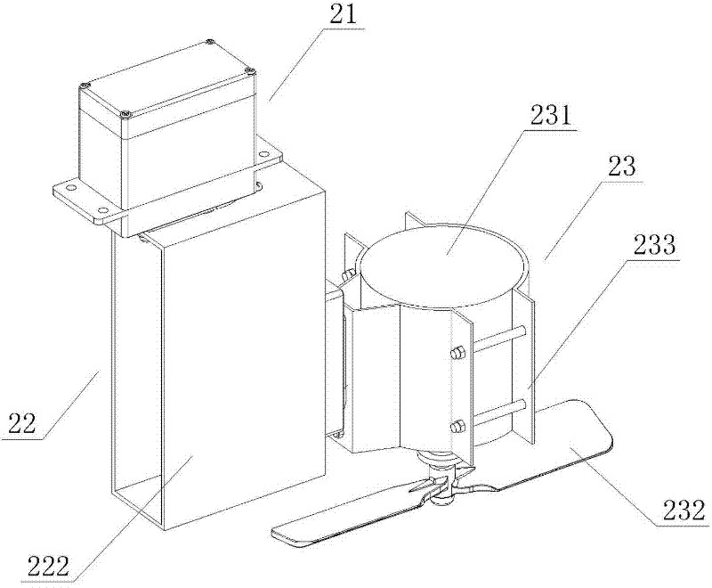
[0026] Such as Figure 1 to Figure 5As shown, the air sampling aircraft of the present invention includes a flight main body 1, a control device and a sampling device installed on the flight main body 1, wherein the control device includes an intelligent control module QRCU, connected with the intelligent control module QRCU for Control and adjust the flight direction of the flight body 1 and the direction positioning module for positioning the sampling position, the power drive module connected with the intelligent control module QRCU for driving the operation of the flight body 1, the air sampling aircraft described in this embodiment is controlled by the intelligent control module QRCU To coordinate control and complete various tasks, the intelligent control module QRCU is a small AT91 single-chip microcomputer, which has powerful functions and has various functions such as collection, analysis, calculation and sending data. It has fast speed, high precision and stability. ...


PUM


Abstract

The invention provides an air sampling aircraft which comprises a flight main body, a control device and a sampling device which are disposed on the flight main body, wherein the control device comprises an intelligent control module, a direction positioning module which is connected to the intelligent control module and is used to control and adjust the flying direction of the flight main body and to position the sampling device, and a power driving module which is connected to the intelligent control module and is used to driving the operation of the flight main body, and the power driving module comprises a first-grade actuator, a second-grade actuator, a driving motor, a propeller, and a driving device. Because a combined structure of the flight main body, the control device, and the air sampling device is employed, not only air samples can be collected automatically, but also the time and regional restriction is broken through; more importantly, with the automatic technology, notonly air sampling by sampling technicians is convenient, but also the life safety of sampling personnel is protected during air sampling under certain specific conditions such as regions with inaccessible and strategic terrain or a lot of toxic gas.

Description

technical field [0001] The invention relates to an air sampler, in particular to an air sampler and a sampling method for high-altitude air sampling, so as to detect and measure possible pollutants in the high-altitude. Background technique [0002] Air samplers are known in the art. The current conventional air sampling method is mainly to carry out on-site sampling by the staff carrying the air sampler, or to set sampling points at designated places, place high-tech analytical instruments, and directly analyze the obtained air. These two sampling methods have their own advantages and disadvantages. The former has high flexibility, but consumes a lot of time, manpower and material resources. Although the latter has high precision and fast speed, it is not flexible in movement and limited in collection range. The important thing is its high cost, which is basically more than one million RMB. In terms of air sampling in dangerous terrains and harsh environments such as toxic...

Claims


Application Information

Patent Timeline
IPC IPC(8): B64C39/02G01N1/22
Inventor 杨当立
Owner 杨当立
Why Eureka
Eureka Blog
Learn More