Buffer type soil gas sampling device

A sampling device and soil gas technology, applied in the sampling device and other directions, can solve the problem of being easily suppressed by the air pressure in the box, and achieve the effect of ensuring reliability, maintaining sealing, and maintaining authenticity

Inactive Publication Date: 2011-11-23
ZHEJIANG ACADEMY OF AGRICULTURE SCIENCES
View PDF4 Cites 41 Cited by
  • Summary
  • Abstract
  • Description
  • Claims
  • Application Information

AI Technical Summary

Problems solved by technology

[0004] The object of the present invention is to provide a self-buffering and adjusting device for the defects that the existing soil gas sampling device is prone to air leakage in the forward or reverse direction of the box and the release of soil gas is easily suppressed by the air pressure in the box due to the lack of a buf...

Method used


Image

  • Buffer type soil gas sampling device
  • Buffer type soil gas sampling device
  • Buffer type soil gas sampling device

Examples


Embodiment 1

[0020] Embodiment 1: (a kind of circular buffer type soil gas sampling device)

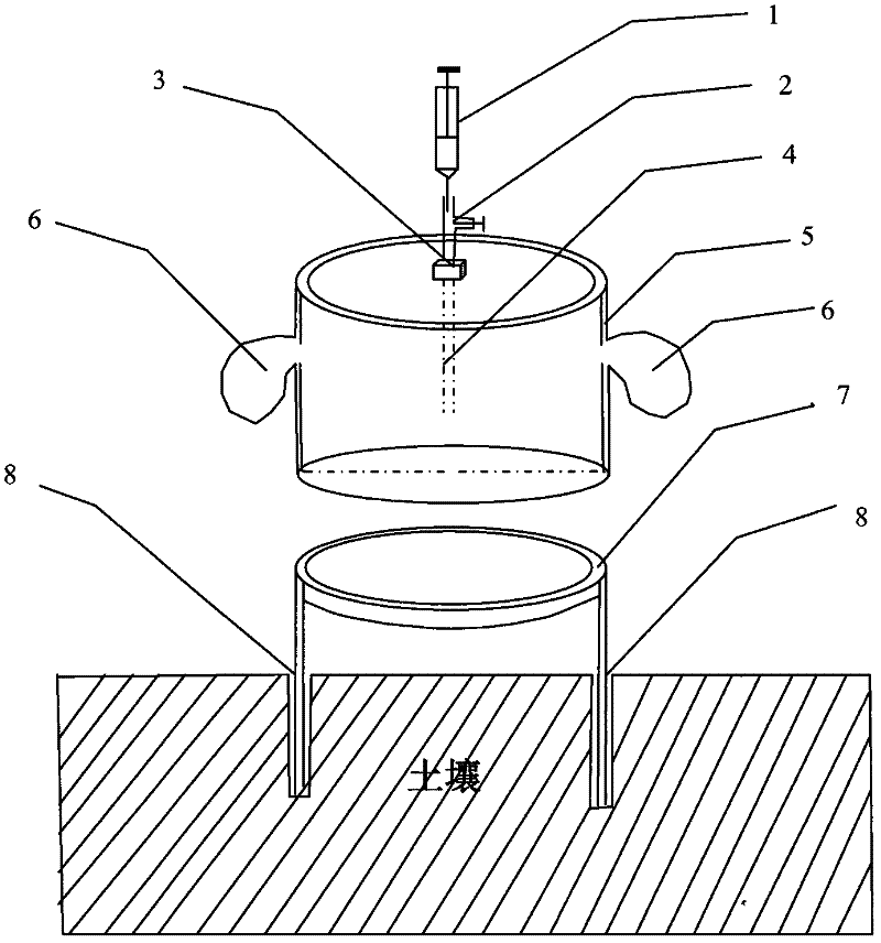
[0021] see figure 1 As shown, the buffer soil gas sampling device is composed of a syringe 1, a three-way valve 2, an air extraction port 3, an air extraction conduit 4, a box body 5, an air bag 6, a water seal tank 7, and a base 8; It is used to extract the stored gas in the box body 5; the air extraction port 3 is a small hole located on the top surface of the box body 5, and the periphery of the hole is sealed with a silica gel plug; the air extraction conduit 4 is a PVC pipe, and its upper end is connected to three It is connected to the lower end of the valve 2, and its lower end extends through the air inlet 3 to the middle part of the box body 5 to obtain the gas sample in the middle part of the box body 5; the box body 5 has a width and height of 1:2, and has a top. A circular box with a surface and a surrounding wall without a bottom surface; 2 airbags 6 are arranged on the surrounding w...

Embodiment 2

[0022] Embodiment 2: (a kind of square buffer type soil gas sampling device)

[0023] In this example, the suction conduit 4 is a small stainless steel tube; the box body 5 is a square box body with a width and height of 1:2; an air bag is respectively arranged on the top surface and the side wall of the box body 5 6. The airbag 6 is a membrane capsule made of plastic film; the remaining components, structure and requirements of the device are the same as those in Embodiment 1.

Embodiment 3

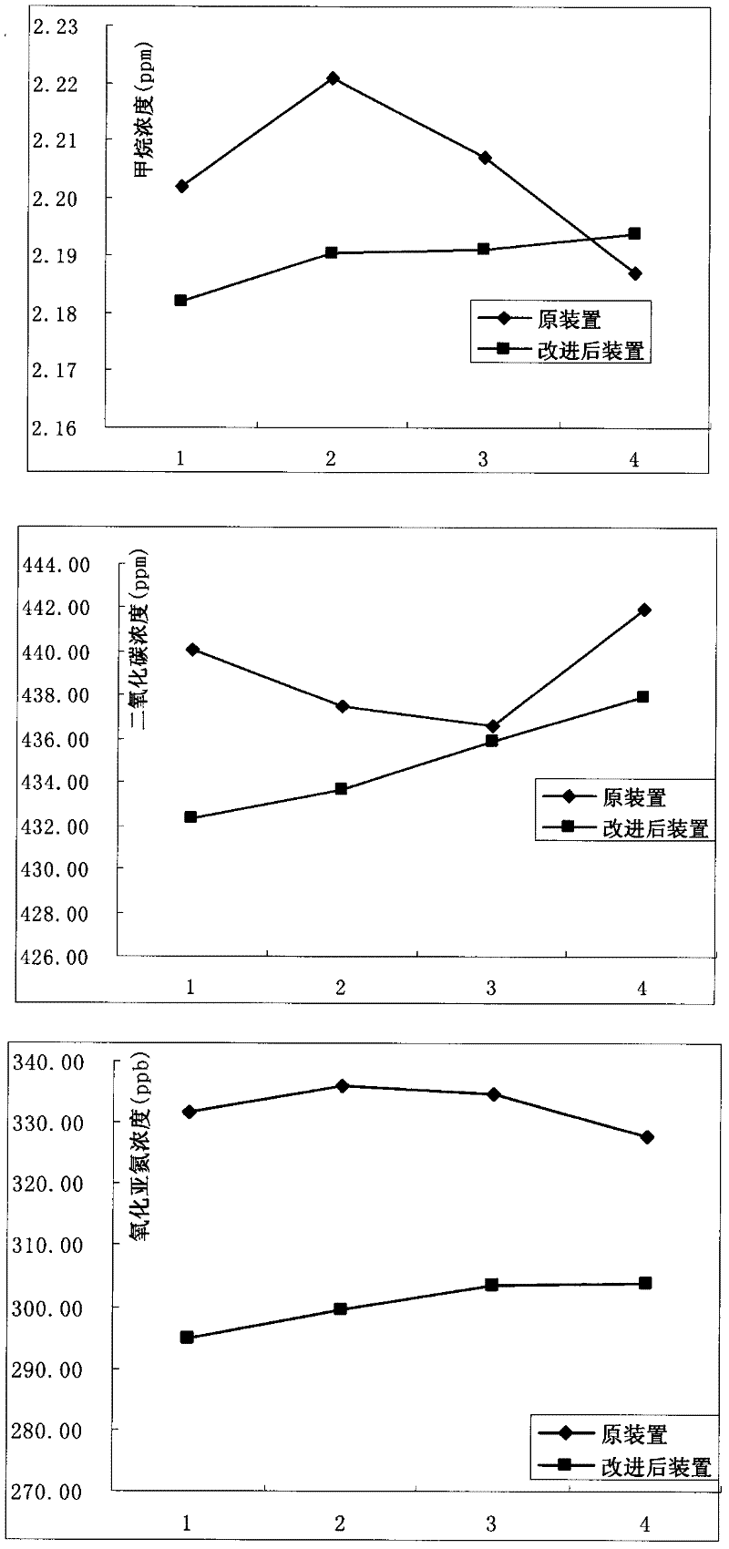
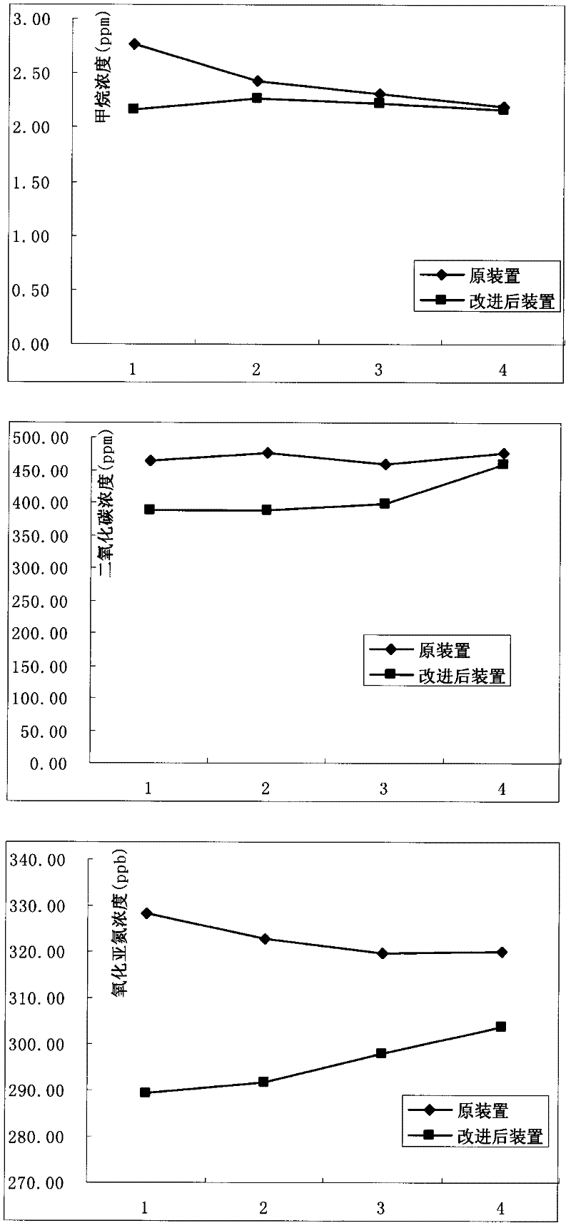
[0024] Embodiment 3: (indoor simulated soil different sampling device measurement effect comparative test)

[0025] Soil sampling device before improvement: conventional (no air bag) soil sampling device;

[0026] Improved soil sampling device: adopt the device of embodiment 1, wherein the maximum expansion volume of the two airbags is ≥ the sampling times set in the experiment × each sampling volume, and the maximum expansion volume of the two airbags in this embodiment is ≥ 240ml;

[0027] In this example, the indoor soil simulation method is adopted, and the base 8 of the soil gas sampling device before and after the improvement is inserted into the soil smoothly, and the surroundings are compacted, and left for 30 minutes; before sampling, the lower end of the box body 5 is seated on the upper end of the base 8 After the water seal tank 7 is inside (the air bag on the box after the improvement needs to squeeze out the air to be in a dry state), immediately fill the water s...


PUM


Abstract

The invention discloses a buffer type soil gas sampling device, belonging to the technical field of soil experimental facilities. The device consists of an injector, a valve, a gas-exhausting hole, a gas-exhausting conduit, a box body, gasbags, a water seal tank and a base. As the gasbags are additionally arranged on the box body, gas pressure inside/outside the box body during a whole storing and sampling process is always maintained in a balance state after the buffer adjustment of the gasbags, the box body is prevented from outward or inward gas leakage, and the quality of gas stored in the box body is maintained; meanwhile, the difficulty that natural release of soil gas is subjected to inhibition is also overcome, the reliability of measured data for gas released by soil is enhanced.The device has the advantages of reasonable design, simplicity for operating and low cost, and can be widely applied to gathering work for greenhouse gas emission in farmland, nudation, grassland andthe like.

Description

technical field [0001] The invention relates to the technical field of soil experiment devices, in particular to a sampling device for releasing gas from field soil. Background technique [0002] Global warming caused by the increase of greenhouse gas concentration in the atmosphere is an important environmental problem facing the world today. Scientists currently attribute the observed global warming to several gases, including carbon dioxide (CO 2 ), methane (CH 4 ) and nitrous oxide (N 2 O) etc. Agriculture is an important source of greenhouse gases, such as the organic matter in the soil is decomposed by microorganisms, that is, CO 2 released into the atmosphere; CH 4 Can be produced by fermentation in permanently flooded farmland; more than half of the world's N 2 O comes from nitrification and denitrification processes in the soil. In order to better understand the direction and trend of climate change, it is necessary to estimate the CO 2 、CH 4 and N 2 O and...

Claims


Application Information

Patent Timeline
IPC IPC(8): G01N1/22
Inventor 陈义吴春艳唐旭杨生茂
Owner ZHEJIANG ACADEMY OF AGRICULTURE SCIENCES
Why Eureka
Try Eureka