Distributed distribution network terminal device

A distribution network terminal and distributed technology, applied in circuit devices, data exchange through path configuration, bus network, etc., can solve the problems of large size, many access cables, limited access capacity, etc., to increase flexibility Effect

Inactive Publication Date: 2011-11-23
AEROSPACE SCI & IND SHENZHEN GROUP
View PDF6 Cites 28 Cited by
  • Summary
  • Abstract
  • Description
  • Claims
  • Application Information

AI Technical Summary

Problems solved by technology

[0005] The present invention aims to solve the technical problems in the prior art that all functional modules of the distribution network terminal are assembled in a chassis, resulting in limited access

Method used


Image

  • Distributed distribution network terminal device
  • Distributed distribution network terminal device
  • Distributed distribution network terminal device

Examples


Embodiment Construction

[0023] In order to make the technical problems, technical solutions and beneficial effects solved by the present invention clearer, the present invention will be further described in detail below in conjunction with the accompanying drawings and embodiments. It should be understood that the specific embodiments described here are only used to explain the present invention, not to limit the present invention.

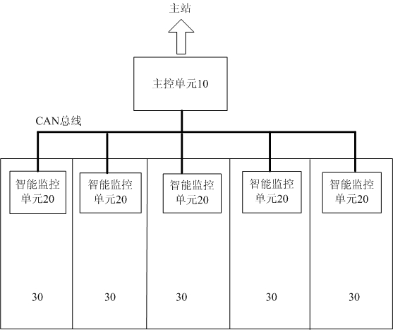
[0024] Such as figure 2 As shown, a distributed distribution network terminal device includes a main control unit 10 communicating with the main station and at least one intelligent monitoring unit 20 electrically connected to the main control unit 10, and the intelligent monitoring unit 20 is installed on the In the switch cabinet or the ring network cabinet 30, the intelligent monitoring unit 20 communicates with the main control unit 10 through the CAN bus. Each intelligent monitoring unit 20 is responsible for real-time monitoring of a corresponding power distribut...


PUM


Abstract

The invention provides a distributed distribution network terminal device for monitoring distribution switch cabinets in real time. The distributed distribution network terminal device comprises a main control unit and at least one intelligent monitoring unit which is electrically connected with the main control unit, wherein the intelligent monitoring units are arranged in the corresponding distribution switch cabinets to be monitored; and the intelligent monitoring units and the main control unit communicate with each other through a controller area network (CAN) bus. By adoption of the technical scheme, the independent intelligent monitoring units are arranged in cabinet bodies of the distribution switch cabinets, and all intelligent monitoring units and one main control unit are connected and communicate with each other through the CAN bus, so the technical problems of limited access capacity, many access cables and large size caused by assembling all functional modules of a distribution terminal in a cabinet are effectively solved.

Description

[0001] technical field [0002] The invention belongs to the technical field of power supply and distribution, and in particular relates to a distributed distribution network terminal device. Background technique [0003] In the existing distribution network automation system, the distribution network terminal device that realizes real-time collection and monitoring of the power distribution switchgear is mainly DTU. There are many power distribution switches in the power distribution switchgear. The DTU device uses one device to realize all distribution Real-time data acquisition and control of the switch, and complete the communication with the remote master station. figure 1 It shows the structure of an existing distribution network terminal, that is, a DTU device. The distribution network terminal device mainly includes a main processing module 11 and several collection modules 12 connected thereto, and each collection module 12 includes a An analog / switch input isolati...

Claims


Application Information

Patent Timeline
IPC IPC(8): H02J13/00H04L12/40
Inventor 赖晓明
Owner AEROSPACE SCI & IND SHENZHEN GROUP
Why Eureka
Try Eureka