Method for optimizing acoustic source array performance

A technology of sound source array and sound source, applied in the direction of seismology, seismic energy generation, instruments, etc. for areas covered by water, which can solve the problem of acoustic signal differentiation

Active Publication Date: 2011-11-23
GECO TECH BV
View PDF9 Cites 2 Cited by
  • Summary
  • Abstract
  • Description
  • Claims
  • Application Information

AI Technical Summary

Problems solved by technology

However, it is not possible with modern compact array structures to distinguish the acoustic signals from neighboring airguns in measurements from unprocessed near-field hydrophones
[0004] Another problem with conventional air guns is the emission of significant acoustic amplitudes outside the frequency range suitable for seismic exploration

Method used


Image

  • Method for optimizing acoustic source array performance
  • Method for optimizing acoustic source array performance
  • Method for optimizing acoustic source array performance

Examples


Embodiment Construction

[0017] In the following description, numerous details are set forth to provide an understanding of the present invention. However, it will be understood by those skilled in the art that the invention may be practiced without these details and that numerous changes or modifications from the described embodiments may be possible.

[0018] The present invention generally relates to techniques used to obtain seismic data in marine environments. This technique helps optimize source array performance for source arrays used in conducting seismic surveys. For example, in one application, the technique facilitates the attenuation of the high frequency output of a sound source by desynchronizing the source trigger. In another aspect of the technique, sound sources can be synchronized using a band-limited notional source signature.

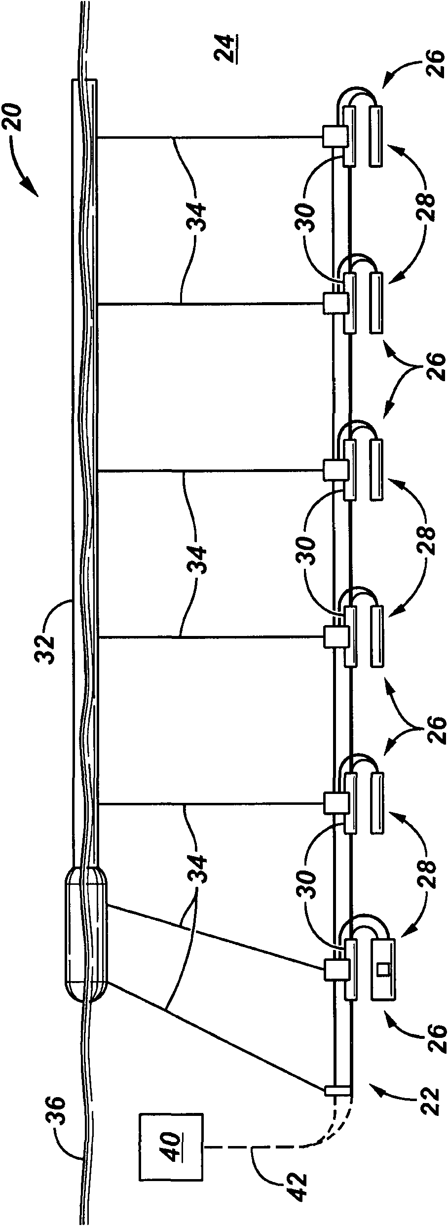
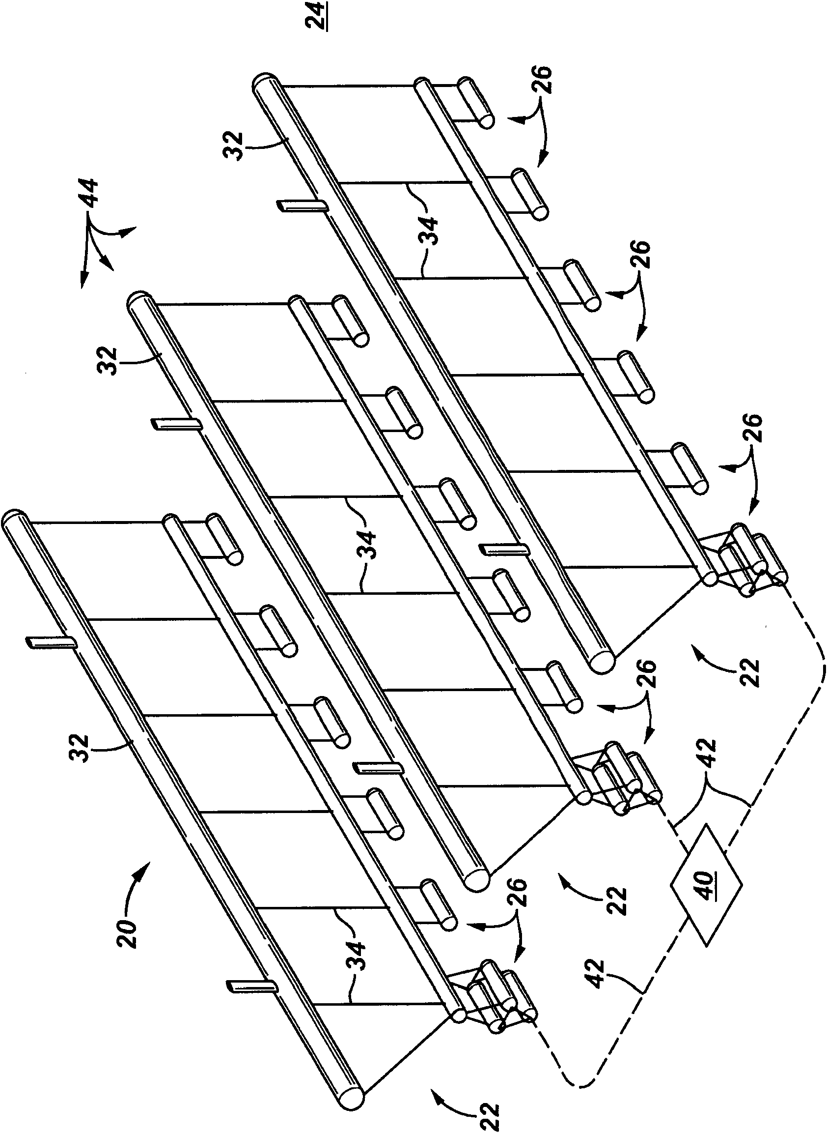
[0019] general reference figure 1 , shows an example of a seismic survey system 20 according to an embodiment of the present invention. As shown, the sy...


PUM


Abstract

A technique facilitates obtaining seismic data in a marine environment. An array of acoustic sources is deployed in a marine environment. The array can be utilized for creating acoustic pulses that facilitate the collection of data on subsea structures. The methodology enables optimization of acoustic source array performance to improve the collection of useful data during a seismic survey.

Description

Background technique [0001] In various marine environments, seismic surveys are performed to gain greater understanding of the geological formations beneath a body of water. An array of marine seismic sources is used to generate acoustic pulses in the water, and hydrophones detect the reflected signals. An ignition controller is used to trigger the ignition of the sound source elements thus synchronizing the main pressure pulses of each element in the desired direction in the far field. For example, triggering can be done so that the main pulse of each element coincides in the far field in the vertical direction. In some applications, the ignition controller implements a time delay to compensate for individual differences in the mechanical triggering mechanism of the sound source elements. Trigger delay can also be used to compensate for geometric differences in source arrays. [0002] One way to quantify mechanical trigger delay is to use a tick sensor. A tick sensor is p...

Claims


Application Information

Patent Timeline
Patent Type & Authority Applications(China)
IPC IPC(8): G01V1/38G01V1/22G01V1/02G01V1/28G01V1/16
CPCG01V1/08G01V1/00G01V1/3861G01V1/006G01V1/3808
Inventor J-F·霍珀斯塔德R·劳斯A·S·梅尔博
Owner GECO TECH BV
Why Eureka
Try Eureka