Semi-automatic short distance cutting machine and its cutting method

A semi-automatic and cutting machine technology, applied in welding equipment, gas flame welding equipment, metal processing equipment, etc., can solve the problems of high operation level, high processing requirements, high technical requirements, etc.

Active Publication Date: 2011-11-30
ZHEJIANG XIZI HEAVY IND MACHINERY
View PDF8 Cites 13 Cited by
  • Summary
  • Abstract
  • Description
  • Claims
  • Application Information

AI Technical Summary

Problems solved by technology

[0002] The cutting of actual section steel, especially the cutting of H-section steel grooves, mostly requires on-site welding butt joint groove workshops. Since the relevant national standards require that the grooves should be uniform, smooth, and free of uneven defects, the previous production methods There are many problems. For example, using manual gas cutting with line drawing or using a semi-automatic gas cutting car to open the bevel. Manual gas cutting requires a high level of operation for workers. Due to the large size of the gas cutting car, it is inconvenient to operate. Also there is no small automatic cutting machine that can have portable equipment, and facilitate on-site operation, and can guarantee the quality of processing
In addition, due to the narrow space in the web of the H-beam and the short groove length, the processing requirements are high, and the technical requirements for the designers in the industry are also higher.
Therefore, no ideal small-scale machine technology for cutting steel structural section steel grooves has been found so far no matter whether it is a patented invention or in the domestic and foreign markets.

Method used


Image

  • Semi-automatic short distance cutting machine and its cutting method
  • Semi-automatic short distance cutting machine and its cutting method
  • Semi-automatic short distance cutting machine and its cutting method

Examples


Embodiment Construction

[0024] The technical contents and implementation methods of the present invention will be further described in detail below in conjunction with the accompanying drawings.

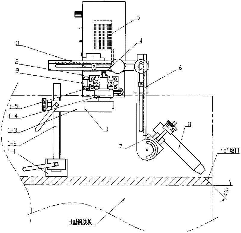
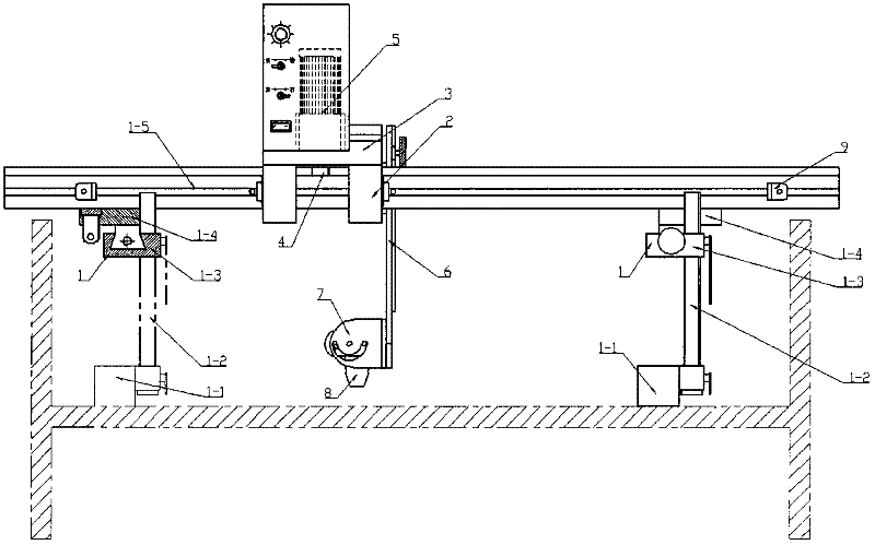
[0025] attached figure 1 , 2 For a preferred embodiment of the present invention, by attaching figure 1 , 2 The structure of the present invention can be clearly described, and the present invention simply utilizes the principle of magnetism—magnetism occurs between the strong magnetic base 1-1 and the processed iron workpiece to fix the cutting machine on the processed iron workpiece , can be used more flexibly in on-site operation, which is incomparable with the existing technology. The torch 8 is installed and arranged on the machine base 3 through a manual fine-tuning device, and the machine base 3 moves linearly along the guide rails 1-5 to complete the cutting task.

[0026] Cutting operation instructions of the semi-automatic short-distance cutting machine: According to the influence of the exter...


PUM


Abstract

The invention provides a semi-automatic short-range cutting machine and a cutting method thereof and relates to a small-sized machine used for cutting a profile steel docking groove. The semi-automatic short-range cutting machine comprises a cutting torch (8), on which a manual micromatic setting device (6) is arranged; the manual micromatic setting device (6) is installed on a machine base (3); the machine base (3) is installed on a rail (1-5) in an adjustable quadrilateral mechanism (1) through a rail slider (2); an angle adjustment device (7) is installed at the bottom of the manual micromatic setting device (6); the machine base (3) is provided with a permanent magnet direct current deceleration motor (5); a gear rack (4) is used for realizing the transmission between the permanent magnet direct current deceleration motor (5) and the rail (1-5) so as to drive the cutting torch (8) to run to finish cutting task; a strong-force magnetic base (1-1) consists of two adjacent rotary fixing points and two rotary or clamped fixing points in the adjustable quadrilateral mechanism (1) so that the whole machine is firmly fixed on a processed workpiece. The invention fills the blank in the prior art; the semi-automatic short-range cutting machine has advantages of simple structure, portability and capability of site operation; and the provided cutting method can effectively guarantee cutting quality.

Description

technical field [0001] A semi-automatic short-distance cutting machine and a cutting method thereof are small-scale equipment used for cutting butt joint grooves of steel structure sections. Background technique [0002] The cutting of actual section steel, especially the cutting of H-section steel grooves, mostly requires on-site welding butt joint groove workshops. Since the relevant national standards require that the grooves should be uniform, smooth, and free of uneven defects, the previous production methods There are many problems. For example, using manual gas cutting with line drawing or using a semi-automatic gas cutting car to open the bevel. Manual gas cutting requires a high level of operation for workers. Due to the large size of the gas cutting car, it is inconvenient to operate. Also there is no small-sized automatic cutting machine that can have portable equipment, and facilitate on-site operation, and can guarantee the quality of processing. In addition, d...

Claims


Application Information

Patent Timeline
Patent Type & Authority Applications(China)
IPC IPC(8): B23K7/00B23K7/10
Inventor 项荣根王俊超何磊
Owner ZHEJIANG XIZI HEAVY IND MACHINERY
Why Eureka
Try Eureka