a woodworking machine

A woodworking lathe and bed technology, applied in the field of woodworking machine tools, can solve the problems of affecting the processing and forming speed and forming effect of wood, unable to fix the added part of wood, poor balance and stability of wood, etc. The effect of quality improvement

Inactive Publication Date: 2011-11-30
陆卫斌
View PDF4 Cites 14 Cited by
  • Summary
  • Abstract
  • Description
  • Claims
  • Application Information

AI Technical Summary

Problems solved by technology

In the processing of various wooden products, most of them need to use woodworking machine tools for processing. Among them, the woodworking machine tools used in wood processing are mainly set with single tool rest and single heel tool rest. The diameter of part of the processed finished product exceeds the diagonal line of the wood cross section. For the common lathe tool rest that mainly fixes the four-edged cylinder of the non-enlarged part,...

Method used


Image

  • a woodworking machine
  • a woodworking machine
  • a woodworking machine

Examples


Embodiment 1

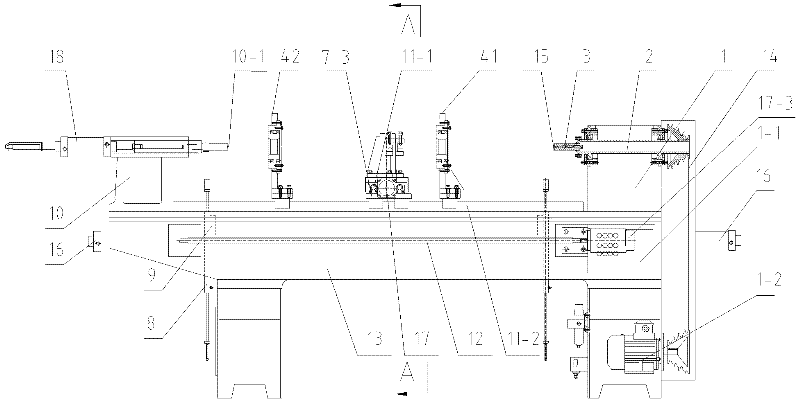
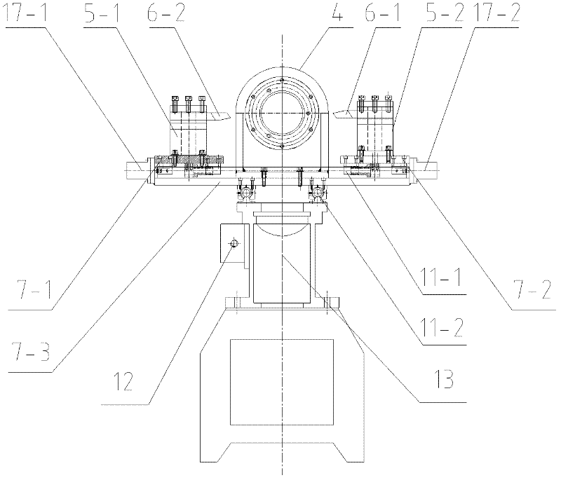
[0038] Such as figure 1 , figure 2 and image 3 As shown, a kind of woodworking lathe, including the headstock 1, the main shaft 2, the clamping head 3, the movable tool holder 4, the tool holder 5, the turning tool 6, the sliding plate 7, the feeding cylinder 8, the rod type upper Material rack 9, tailstock 10, guide rail 11, lead screw 12, bed 13, stepping motor 17; wherein, the control panel 1-1 is set outside the headstock 1, and the frequency conversion motor for driving the main shaft 2 is set inside the headstock 1 1-2, the frequency conversion motor 1-2 is connected to the main shaft 2 through a transmission belt 14; the inner end of the main shaft 2 is fixed with a chuck 3; the top of the chuck 3 is evenly provided with four cone points 15; the bed 13 is provided with two groups of rod-type feeding racks 9, tailstock 10, guide rail 11, and lead screw 12; the upper end of the rod-type feeding rack 9 is provided with a 90 ° V-shaped groove (not shown), and its lower ...

Embodiment 2

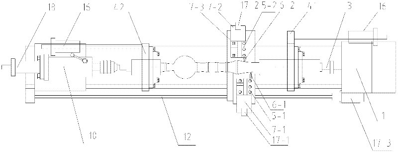
[0048] Such as Figure 5 , Figure 6 and Figure 7 As shown, a kind of woodworking lathe, including the headstock 1, the main shaft 2, the clamping head 3, the movable tool holder 4, the tool holder 5, the turning tool 6, the sliding plate 7, the feeding cylinder 8, the rod type upper Material rack 9, tailstock 10, guide rail 11, lead screw 12, bed 13, stepping motor 17; wherein, the control panel 1-1 is set outside the headstock 1, and the frequency conversion motor for driving the main shaft 2 is set inside the headstock 1 1-2, the frequency conversion motor 1-2 is connected to the main shaft 2 through a transmission belt 14; the inner end of the main shaft 2 is fixed with a chuck 3; the top of the chuck 3 is evenly provided with four cone points 15; the bed 13 is provided with two groups of rod-type feeding racks 9, tailstock 10, guide rail 11, and lead screw 12; the upper end of the rod-type feeding rack 9 is provided with a 90 ° V-shaped groove (not shown), and its lowe...


PUM


Abstract

The invention relates to a woodworking machine tool, which belongs to the field of woodworking machinery and equipment, and comprises an interconnected headstock, a spindle, a chuck, a tool holder, a tool holder, a turning tool, a sliding plate, a feeding cylinder, a feeding rack, a tailstock, and a bed Body, guide rail, lead screw, stepping motor, wherein, the number of said tool holders is more than two, which are respectively arranged on the sliding plate; on the sliding plate; the number of the turning tool is the same as the number of the tool holder, the turning tool is arranged in a direction perpendicular to the axis of the lathe, and the tip of the turning tool is along the axis of the lathe The parallel directions are misaligned with each other. Compared with the prior art, the present invention has a novel structure and simple operation, effectively overcomes the defects of single knife and single knife holder for wood production and processing, greatly improves the processing efficiency, increases the smoothness of the finished product, and correspondingly reduces the economic cost. The invention is suitable for popularization and application in wood processing related fields.

Description

technical field [0001] The invention relates to a woodworking machine tool, which belongs to the field of woodworking machinery equipment. Background technique [0002] At present, with the development of the economy, people pay more and more attention to environmental protection. In many buildings and personal home decoration, the demand for wooden products is gradually increasing. In the processing of various wooden products, most of them need to use woodworking machine tools for processing. Among them, the woodworking machine tools used in wood processing are mainly set with single tool rest and single heel tool rest. The diameter of part of the processed finished product exceeds the diagonal line of the wood cross section. For the common lathe tool rest that mainly fixes the four-edged cylinder of the non-enlarged part, it cannot make the enlarged part of the wood pass through the section smoothly. Fixing a large part of the wood will affect the molding speed and moldin...

Claims


Application Information

Patent Timeline
IPC IPC(8): B27C7/00
Inventor 陆卫斌
Owner 陆卫斌
Why Eureka
Try Eureka