A New Type of Radiator Thermal Resistance Flow Resistance Test Equipment

A technology for testing equipment and radiators, which is applied in the testing of mechanical components, testing of machine/structural components, and instruments. It is unfavorable for thyristor protection and other problems, and achieves the effects of simple structure, reduced water temperature fluctuation, and strong practicability

Active Publication Date: 2011-11-30
CHINA ELECTRIC POWER RES INST +2
View PDF11 Cites 10 Cited by
  • Summary
  • Abstract
  • Description
  • Claims
  • Application Information

AI Technical Summary

Problems solved by technology

[0002] Traditional radiator thermal resistance flow resistance testing equipment is generally used to test air-cooled radiators or heat pipe radiators. The measurement of thermal resistance and flow resistance of water-cooled radiators is rarely applied to thyristor radiators, which do not have thermal resistance of thyristor radiators. Test conditions: First, the converter valve thyristor and radiator are generally press-fitted, and the press-fitting force is very high. The press-fitting force of the 6-inch thyristor radiator press-fitting structure is 187kN, and the traditional test equipment does not have the press-fitting conditions; Both thermal resistance and flow resistance measurement platforms collect temperature points on the outer edge of the radiator radius, and calculate the thermal resistance of the radiator with the average temperature of multiple points. The thermal resistance of the radiator obtained by this test method is smaller than the actual thermal resistance value, which is not Conducive to the protection of thyristor

Method used


Image

  • A New Type of Radiator Thermal Resistance Flow Resistance Test Equipment
  • A New Type of Radiator Thermal Resistance Flow Resistance Test Equipment
  • A New Type of Radiator Thermal Resistance Flow Resistance Test Equipment

Examples


Embodiment 1

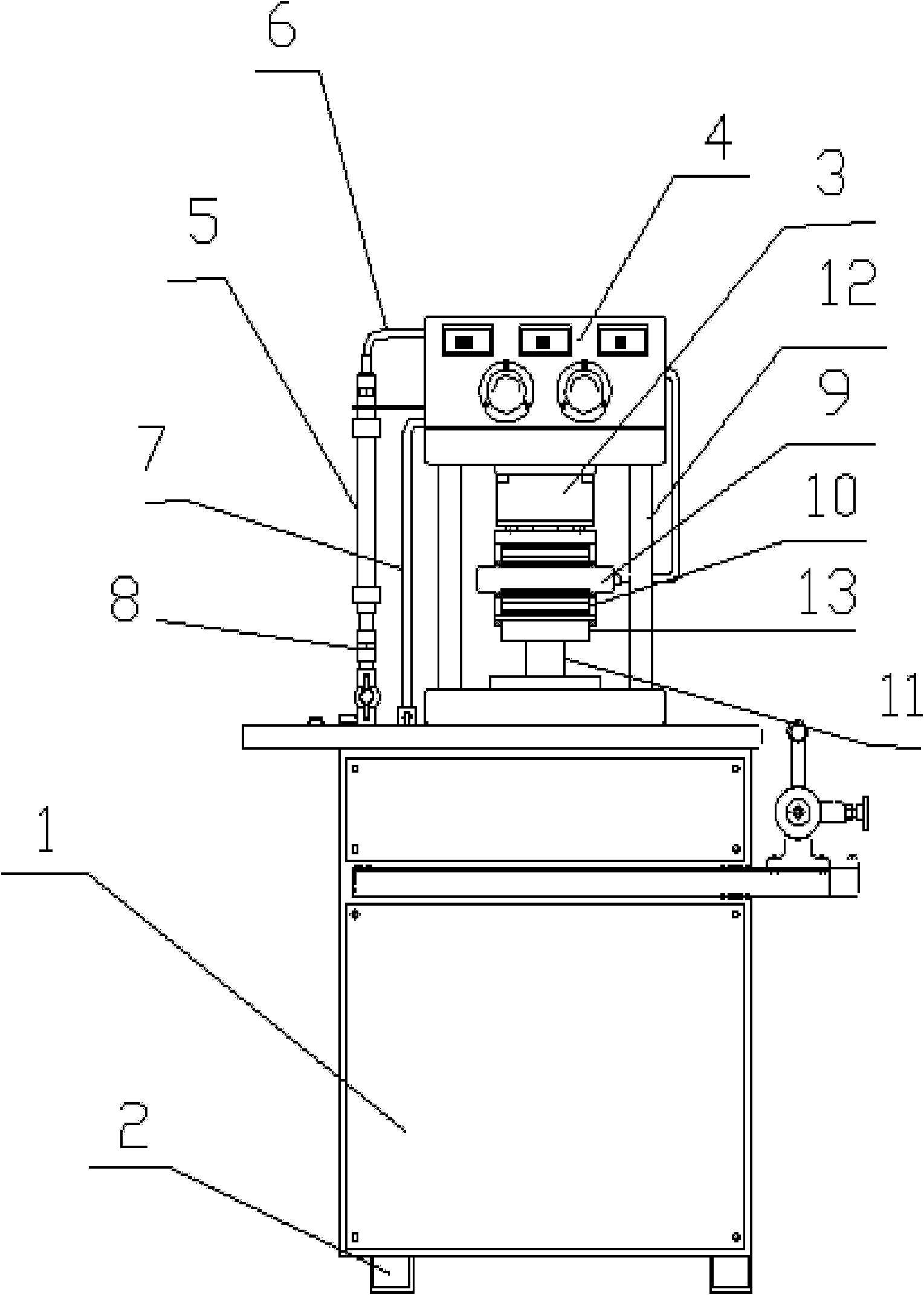
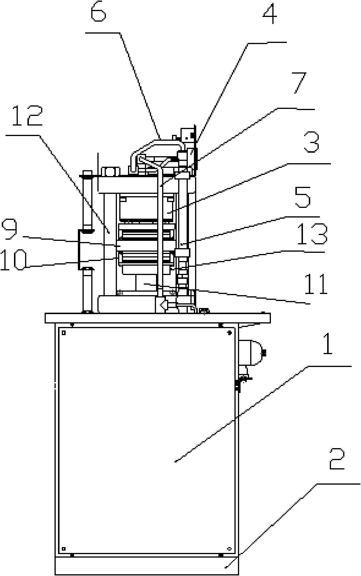
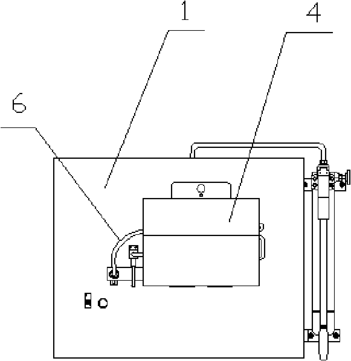
[0026] Such as Figure 1-4 As shown, the invention of this example is a new type of radiator thermal resistance flow resistance testing equipment, which includes an equipment box 1 and a base 2, and the equipment box 1 includes a thyristor radiator press-fit part 3, a water circulation system, and testing and collection equipment. 4. The equipment box 1 includes power equipment and a water storage tank; the thyristor radiator press-fit part 3 is installed on the equipment box body 1 through the fixing frame 12, and one end of the thyristor radiator press-fit part 3 is connected to the equipment box body 1, The other end is connected with the test and collection equipment 4, and the test and collection equipment 4 is connected with the reservoir through a water circulation system, and a water circulation system is provided between the thyristor radiator pressing part 3 and the test and collection equipment 4; the thyristor radiator The press-fit part 3 includes a hydraulic mech...


PUM


Abstract

The invention relates to the field of water cooling system in power electronics, and more specifically relates to a novel thermal resistance and flow resistance test device for a radiator. The device comprises a device box and a pedestal, wherein a thyristor radiator press mounting piece, a water circulation system and a test and acquisition device are arranged on the device box, and a power supply device and a reservoir are arranged in the device box; the thyristor radiator press mounting piece is arranged on the device box, one end of the thyristor radiator press mounting piece is connected with the device box while the other end of the thyristor radiator press mounting piece is connected with the test and acquisition device, the test and acquisition device is connected with the reservoir through the water circulation system, and the water circulation system is arranged between the thyristor radiator press mounting piece and the test and acquisition device; and the thermal resistance and flow resistance test device can synchronously perform thermal resistance test and flow resistance test, and uses a heating block to substitute thyristor elements, so that a thermal resistance curve and a flow resistance curve of the thyristor radiator can be obtained within short time, and basis for designing a DC (direct current) transmission converter valve cooling system is provided.

Description

Technical field: [0001] The invention relates to the field of water-cooling systems in power electronics, and more particularly relates to a novel radiator thermal resistance flow resistance testing device. Background technique: [0002] Traditional radiator thermal resistance flow resistance testing equipment is generally used to test air-cooled radiators or heat pipe radiators. The measurement of thermal resistance and flow resistance of water-cooled radiators is rarely applied to thyristor radiators, which do not have thermal resistance of thyristor radiators. Test conditions: First, the converter valve thyristor and radiator are generally press-fitted, and the press-fitting force is very high. The press-fitting force of the 6-inch thyristor radiator press-fitting structure is 187kN, and the traditional test equipment does not have the press-fitting conditions; Both thermal resistance and flow resistance measurement platforms collect temperature points on the outer edge o...

Claims


Application Information

Patent Timeline
Patent Type & Authority Applications(China)
IPC IPC(8): G01N25/20G01M13/00
Inventor 周建辉查鲲鹏张静胡德诚
Owner CHINA ELECTRIC POWER RES INST
Why Eureka
Try Eureka