Springback cause analysis method, springback cause analysis device, springback cause analysis program and recording medium

A technique of cause analysis and rebound, applied in the direction of comprehensive factory control, instrumentation, CAD technology, etc., can solve problems such as difficult to correctly grasp the rebound of extruded molded products, and achieve the effect of shortening the research time

Active Publication Date: 2011-11-30
NIPPON STEEL CORP
View PDF8 Cites 11 Cited by
  • Summary
  • Abstract
  • Description
  • Claims
  • Application Information

AI Technical Summary

Problems solved by technology

However, it is difficult to accurately grasp the cause of springback of extruded molded products in the design stage before actual forming tests are performed.

Method used


Image

  • Springback cause analysis method, springback cause analysis device, springback cause analysis program and recording medium
  • Springback cause analysis method, springback cause analysis device, springback cause analysis program and recording medium
  • Springback cause analysis method, springback cause analysis device, springback cause analysis program and recording medium

Examples


Embodiment 1

[0104] (Example 1: Example where all stress components are set to zero)

[0105] Figure 4 It is a perspective view showing the shape of the extrusion-molded product of Example 1 of the present invention. First, extrusion forming analysis processing is performed using LS-DYNA, a commercially available sheet forming simulation analysis software based on the finite element method. As the properties of the metal plate, the data of a high-strength steel plate with a plate thickness of 1.6 mm and a tensile strength of 590 MPa was used. In addition, the shape of the die (die, punch, holder) is modeled as a shell element and analyzed as a rigid body. The die gap was set to 0 mm. The coefficient of friction was set to 0.15. The forming load was set at 3000kN.

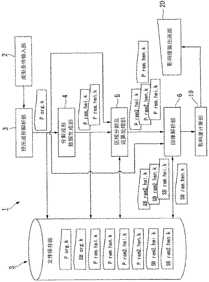
[0106] The program for generating independent decomposition data decomposed into in-plane stress components (mean stress) and bending moment components (deviation stress) takes in a file outputting stress and deflection ob...

Embodiment 2

[0116] (Example 2: Example where only σy of the in-plane stress component is set to zero)

[0117] In the first embodiment described above, the calculation process of multiplying all the stress components of all the integration points of the elements belonging to each region by the coefficient zero is performed, and various modifications are shown below. Figure 8A The shape of the extruded product of Example 2 is shown. Figure 8B express Figure 8A The segmented area of ​​the extrusion is shown. exist Figure 8B In , three points represented by circles are used as fixed points, and independent decomposition data with only in-plane stress components are generated from the original data to analyze the in-plane stress. As the amount of springback, the amount of displacement in the Z-axis direction (direction perpendicular to the paper surface) at the portion indicated by Za was evaluated.

[0118] Divide the entire extruded product into five regions from region 801 to regio...

Embodiment 3

[0122] (Example 3: Example with fixed point changed)

[0123]In Example 3, an extruded product having the same shape as that used in Example 2, Figure 9A Extrusions shown. In this embodiment 3, the embodiment 2 Figure 8B The positions of the fixed points are shown as Figure 9B Change as shown. First, in the same manner as in Example 1, an arithmetic process of multiplying all stress components of all integration points of elements belonging to each region by a coefficient of zero is performed. Table 2 shows the analysis results thus obtained. By changing the position of the fixed point, it is possible to discriminate whether the warp appears to be originally due to the shape or is actually warped. In addition, the change of the fixed point is performed at the final stage of calculation, and it is not necessary to recalculate from the beginning.

[0124] [Table 2]

[0125] Analytical conditions and analytical results of embodiment 3

[0126]


PUM

PropertyMeasurementUnit
thicknessaaaaaaaaaa
tensile strengthaaaaaaaaaa

Abstract

A springback occurrence cause analyzing method includes a forming analyzing step of calculating forming data about an object to be formed, a component resolving step of resolving the stress component in one direction into a parallel stress component and a bending moment component, a pre-calculation independent resolution forming data creating step of creating pre-calculation independent resolution forming data, a calculating step of creating post-calculation independent resolution forming data, a springback analyzing step of analyzing a first springback shape and a second springback shape, a degree-of-influence calculating step of determining the degree of influence of the stress of each region calculated from the shape before the springback included in the forming data and the first and second springback shapes on the springback deformation, and a display step of displaying the degree of influence on the springback deformation.

Description

technical field [0001] The present invention relates to a springback cause analysis method, a springback method, and a springback method for analyzing the cause of springback occurring on a molded product when extruding automobile parts or home appliance parts with steel plates or other metal plates. A rebound cause analysis device, a rebound cause analysis program and a recording medium. A steel plate will be described below, but the present invention can also be applied to other metal plates, plastic plates, wire rods, and the like. [0002] This application claims priority based on Japanese Patent Application No. 2008-329099 for which it applied in Japan on December 25, 2008, and uses the content here. Background technique [0003] Many automotive parts, such as doors and bumpers, and home appliance parts, such as refrigerator panels, are produced by extrusion molding steel or other metal plates. In recent years, there has been an increasing demand for weight reduction ...

Claims


Application Information

Patent Timeline
Patent Type & Authority Applications(China)
IPC IPC(8): B21D22/00G06F17/50
CPCB21D22/20G06F17/5018Y02T10/82G06F2217/16G06F30/15G06F30/23G06F2111/10G06F2113/24G06F2119/18Y02P90/02B21D22/00G06Q50/04
Inventor 宫城隆司田中康治小川操
Owner NIPPON STEEL CORP
Why Eureka
Try Eureka