
Method for diagnosing regeneration failure of exhaust gas purification device

一种排气净化装置、诊断方法的技术

Inactive Publication Date: 2011-11-30
HINO MOTORS LTD
View PDF5 Cites 3 Cited by
  • Summary
  • Abstract
  • Description
  • Claims
  • Application Information

AI Technical Summary

Problems solved by technology

[0011] However, in the past, instead of performing forced regeneration through the above-mentioned filter regeneration mechanism, after the regeneration is completed, it is actually confirmed whether the regeneration of the particulate filter is completed normally or in a state of regeneration failure. The regeneration failure of the particulate filter cannot be applied to on-board Diagnosis (onboard diagnosis: Carry out fault diagnosis of the exhaust gas countermeasure system of the car, in the case of a fault, notify the driver of the fault, and record the alarm system of the fault location, etc.)

Method used


Image

  • Method for diagnosing regeneration failure of exhaust gas purification device
  • Method for diagnosing regeneration failure of exhaust gas purification device
  • Method for diagnosing regeneration failure of exhaust gas purification device

Examples


Embodiment Construction

[0039] Hereinafter, embodiments of the present invention will be described with reference to the drawings.

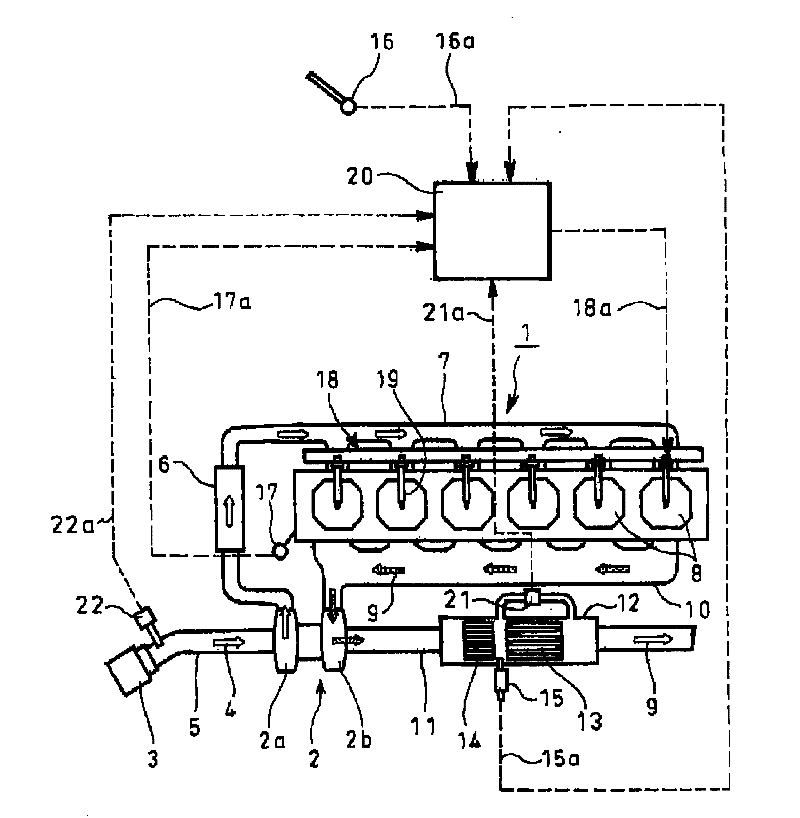
[0040] Figure 1 ~ Figure 3 An example of an embodiment of the present invention is shown. figure 1 The 1 in it represents a diesel engine equipped with a turbocharger 2, the intake air 4 introduced from the air cleaner 3 is delivered to the compressor 2a of the above-mentioned turbocharger 2 through the intake pipe 5, and after being pressurized by the compressor 2a The intake air 4 is transported to the intercooler 6 and cooled, and the intake air 4 is guided from the intercooler 6 to the intake manifold 7 and distributed to each cylinder of the diesel engine 1 (in figure 1 exemplifies the case of an inline 6 cylinder).

[0041] The exhaust gas 9 discharged from each cylinder 8 of the diesel engine 1 is sent to the turbine 2 b of the turbocharger 2 through the exhaust manifold 10 , and the exhaust gas 9 driven by the turbine 2 b is discharged outside the vehicle thr...


PUM


Abstract

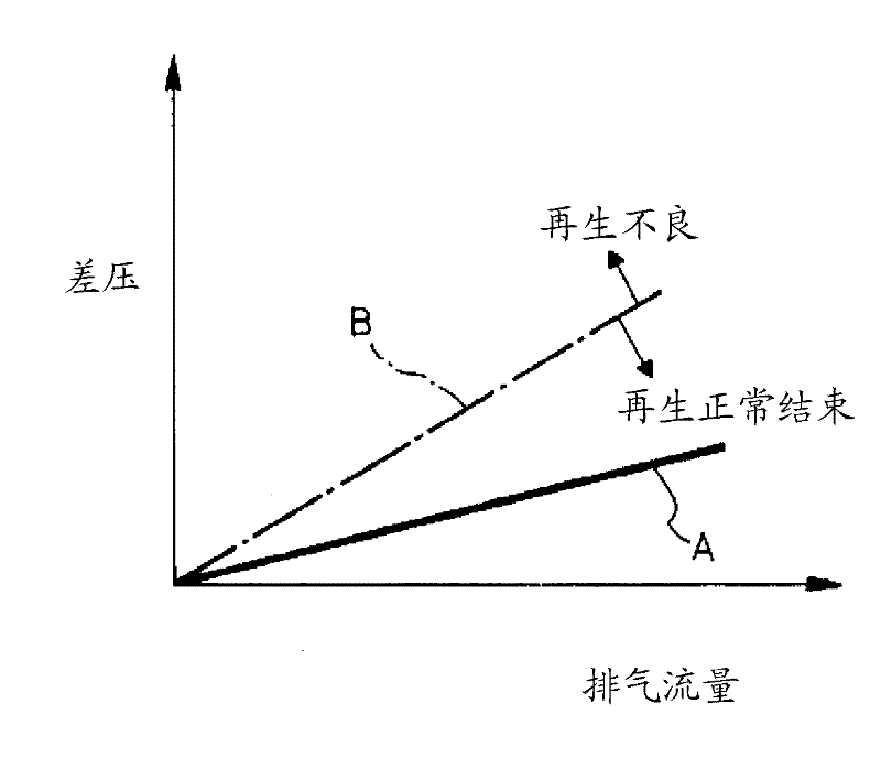
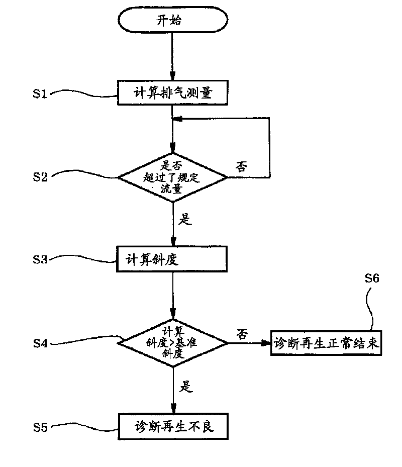
Provided is a method of diagnosing regeneration failure of an exhaust emission control device including filter regenerating means for forcibly heating a particulate filter 13 so as to burn off captured particulates. An exhaust flow rate to the particulate filter 13 and a differential pressure between entry and exit sides of the particulate filter 13 are obtained to calculate a gradient of change in the differential pressure relative to change in the exhaust flow rate. The calculated gradient is compared with a predetermined reference gradient to diagnose the particulate filter 13 as having regeneration failure when the calculated gradient exceeds the reference gradient.

Description

technical field [0001] The invention relates to a method for diagnosing regeneration failure of an exhaust purification device. Background technique [0002] Particulates (particulate matter) discharged from diesel engines are mainly composed of coal composed of carbon and SOF components (soluble organic components) composed of high-boiling hydrocarbons, and contain a small amount of sulfate (fog-like sulfuric acid component) ) composition, conventionally, as a countermeasure to reduce such particles, a particle filter is installed in the middle of the exhaust pipe through which the exhaust gas flows. [0003] This particulate filter has a porous honeycomb structure made of ceramics such as zeolite. The inlets of the flow paths divided into grids are sealed alternately, and the outlets of the flow paths with unsealed inlets are sealed. The exhaust gas after the porous thin wall dividing each flow path is discharged to the downstream side. [0004] Moreover, since the parti...

Claims


Application Information

Patent Timeline
Patent Type & Authority Applications(China)
IPC IPC(8): F01N3/02B01D53/94F02D45/00B01D46/42
CPCB01D53/9495F02D41/029F01N2013/026B01D46/42F01N3/023F01N9/002F01N11/002B01D46/448F02D41/1446F01N3/106B01D46/0057F01N13/0097F01N2550/04B01D46/446F01N11/00B01D2257/7022F02B37/00B01D2279/30F01N2900/1406F01N2900/0418F02D41/405B01D46/0063Y02T10/47F02D41/22F02D41/1445F01N2560/08F01N2900/0421B01D53/944F01N3/103Y02T10/40B01D46/66B01D46/84
Inventor 小泉亘成田洋纪南川仁一
Owner HINO MOTORS LTD
Learn More