
Safety control method of servo control system for stationary blades of trt unit

A technology of servo control system and safety control, which is applied in the direction of fluid pressure actuation system components, mechanical equipment, blast furnace parts, etc., can solve problems such as the normal operation of TRT units that threaten the safety of blast furnace smelting production

Active Publication Date: 2011-12-07
XIAN SHAANGU POWER
View PDF5 Cites 11 Cited by
  • Summary
  • Abstract
  • Description
  • Claims
  • Application Information

AI Technical Summary

Problems solved by technology

During the normal operation of the existing TRT unit, the top pressure of the blast furnace (referred to as blast furnace top pressure) is controlled by the stator blade servo control system of the TRT unit. This control method can meet the blast furnace top pressure when the unit stator blade servo control system is normal. However, when an emergency failure occurs in the stator servo control system, such as the failure of the stator servo controller, the failure of the electro-hydraulic servo valve, etc., it will cause the TRT unit stator actuator to open or close quickly, which will greatly The threat to the production safety of blast furnace smelting and the normal operation of TRT unit
But at present, there is no effective method to solve the control of the top pressure of the blast furnace when the servo control system of the stator blades has an emergency failure.

Method used


Image

  • Safety control method of servo control system for stationary blades of trt unit
  • Safety control method of servo control system for stationary blades of trt unit
  • Safety control method of servo control system for stationary blades of trt unit

Examples


Embodiment Construction

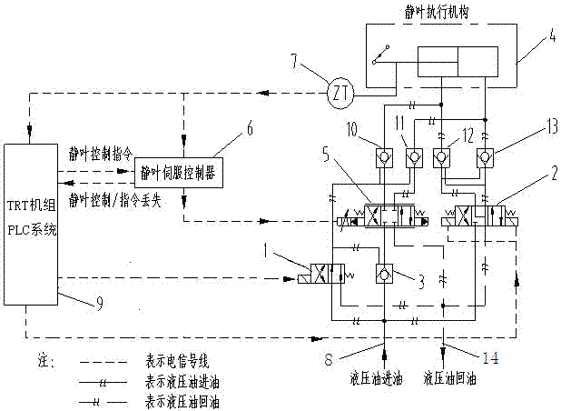
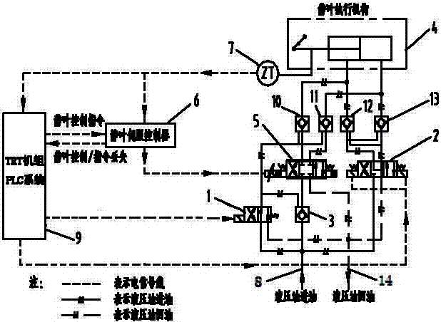
[0022] refer to figure 1 , applying the present invention to the TRT unit stator servo system: the system includes a stator retaining device and a stator servo control system, the stator retaining device includes a retaining solenoid valve 1, a bypass solenoid valve 2, a first liquid control check valve 3, second hydraulic control check valve 10, third hydraulic control check valve 11, fourth hydraulic control check valve 12, fifth hydraulic control check valve 13, vane actuator 4; The vane servo control system includes electro-hydraulic servo valve 5, vane servo controller 6 and vane position sensor 7; the three control signal output terminals of the PLC system 9 of the TRT unit are respectively connected to the vane servo controller 6 and the position holding solenoid valve 1. Bypass solenoid valve 2; the vane actuator 4 is connected to the vane position sensor 7, and the two feedback signal output ends of the vane position sensor 7 are respectively connected to the PLC syst...


PUM


Abstract

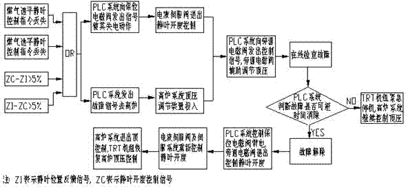
The invention discloses a safety control method for a TRT (Blast Furnace Top Gas Recovery Turbine Unit) fixed blade servo control system. In the method, when a TRT unit runs normally, blast furnace top pressure is adjusted and controlled by the TRT unit fixed blade servo control system; when the TRT unit fixed blade system fails, an electro-hydraulic servo valve quits the control over a fixed blade executing mechanism; a PLC (Programmable Logic Controller) system of the TRT unit outputs a control signal to a bypass electromagnetic valve; the furnace top pressure is restored to be stable undermain adjustment of a blast furnace pressure reducing valve bank and auxiliary adjustment of the bypass electromagnetic valve; operating personnel check on line and manually repair; and if the system cannot be normally restored in a short time, the TRT unit is emergently stopped. According to the method disclosed by the invention, the fixed blade servo system can be checked without stop, the reason of failure and the finally adopted measure are determined, and unnecessary frequent stop of the TRT unit can be avoided. By applying the method, the safety of the system during emergency failure of the fixed blade servo control system can be greatly enhanced; and according to site validation put into operation, the production safety of blast furnace smelting is greatly guaranteed by the method.

Description

technical field [0001] The invention belongs to the field of a blast furnace gas residual pressure energy recovery device (TRT unit for short), and relates to a safety control method, in particular to a safety control method for a stator blade servo control system of a TRT unit. Background technique [0002] Blast furnace smelting is the pillar of the iron and steel industry. TRT unit is a major energy-saving equipment for blast furnace smelting. With the rapid development of industrial control technology, the safety requirements for equipment are constantly improving. Interfere with the normal production of the blast furnace, but also maximize power generation. During the normal operation of the existing TRT unit, the top pressure of the blast furnace (referred to as blast furnace top pressure) is controlled by the stator blade servo control system of the TRT unit. This control method can meet the blast furnace top pressure when the unit stator blade servo control system is...

Claims


Application Information

Patent Timeline
IPC IPC(8): C21B7/00F15B21/08
Inventor 张亚军王航张保平王东升刘宁张利平郑望张娜
Owner XIAN SHAANGU POWER
Learn More