Ferromagnetic cable metal cross-sectional area loss detection method and device

A cross-sectional, ferromagnetic technology, applied in the field of non-destructive testing, can solve the problems of increasing the volume of the magnetization system, the influence of the detection speed is large, and the adjustment of the magnetic circuit is complicated, and achieves the effects of small size, reduced weight, and high magnetization efficiency.

Inactive Publication Date: 2011-12-07
HUAZHONG UNIV OF SCI & TECH
View PDF4 Cites 9 Cited by
  • Summary
  • Abstract
  • Description
  • Claims
  • Application Information

AI Technical Summary

Problems solved by technology

In the above detection method, the magnetic flux detection method is due to the external magnetic source, that is, the magnetic field generated by the permanent magnet or the DC coil does not directly act on the cable under test, but the magnetic flux is introduced into the cable through a certain magnetic circuit design. , due to the existence of leakage flux, it will inevitably cause loss of magnetic energy. In order to meet the magnetization requirements of the detection method, the magnetization energy must be increased, so that the volume and weight of the entire magnetization system will increase. In the main flux detection method, due to Only the coil method can be used to induce the change of the magnetic field, which is greatly affected by the detection speed; the magnetic bridge circuit method uses the integration of multiple magnetic circuits, and the adjustment of the entire magnetic circuit is complicated in order to achieve the linear operating point of the magnetic circuit.

Method used


Image

  • Ferromagnetic cable metal cross-sectional area loss detection method and device
  • Ferromagnetic cable metal cross-sectional area loss detection method and device
  • Ferromagnetic cable metal cross-sectional area loss detection method and device

Examples


Embodiment Construction

[0023] The present invention is described in more detail below by means of examples, but the following examples are only illustrative, and the protection scope of the present invention is not limited by these examples.

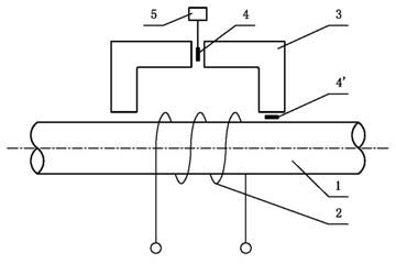
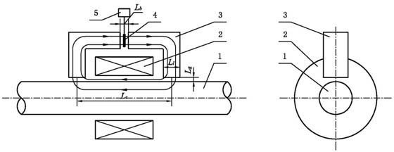
[0024] Such as figure 1 As shown, the cable connected to the DC power supply is wound on the tested cable 1 as a DC magnetizing coil 2, and one or more armature groups 3 are arranged along the circumferential direction of the cable 1 (the number of armature groups can be 1 to 32), Each armature group 3 consists of two symmetrically arranged Type armature blocks, each armature group 3 across the magnetized coil 2, two symmetrically arranged in each armature group 3 Arrange a magnetic sensitive element 4 in the gap reserved between the armature blocks or arrange a magnetic sensitive element 4' in the gap between the end of the armature group 3 and the cable 1; turn on the DC power supply, the cable 1 will be magnetized by the DC coil 2, A magnetic circuit is...


PUM


Abstract

The invention discloses a method and device for detecting loss of metal cross section area of a ferromagnetic cable rope. The method provided by the invention comprises the following steps of: winding a cable which is connected with a direct-current power supply on a detected cable rope to be used as a direct-current magnetizing coil; distributing an armature group and a magnetism-sensitive element along the circumferential direction of the cable rope; switching on a direct-current power supply and magnetizing the cable rope by a direct-current coil to form a magnetic circuit with the armature group; measuring a magnetic induction intensity value in the circuit by the magnetism-sensitive element which is placed in the magnetic circuit and outputting the value in the form of voltage; obtaining a measuring coefficient through comparing the change of voltages which are output by the magnetism-sensitive element before and after a standard sample is inserted so that the detection of the loss of the metal cross section area of the cable rope is realized. The device provided by the invention comprises the magnetism-sensitive element, the magnetizing coil, a data processor and one or morearmature groups; and each armature group is composed of two symmetrical inverted-L-shaped armatures. By utilizing a way of internally placing a magnetic source, a magnetic field generated by the magnetizing coil is directly acted on the detected cable rope so that a magnetic system needed by the detection method has the advantages of small volume, light weight and convenience for adjusting.

Description

technical field [0001] The invention belongs to the non-destructive detection technology, and relates to a method and a device for detecting the metal cross-sectional area loss of ferromagnetic cables, which are used for detecting the wear and corrosion states of ferromagnetic cables such as steel wire ropes and stay cables. Background technique [0002] Ferromagnetic cables include steel wire ropes, bridge cables, amusement facility cables, etc. As a key load-bearing component, they are widely used in coal mines, metallurgy, construction, transportation, tourism and other industries. Abrasion, or cable corrosion due to external environmental factors, the above two situations will cause the metal cross-sectional area of ​​the cable to decrease, thereby reducing the effective load-bearing cross-sectional area of ​​the cable, and endangering the safe operation of the equipment. Therefore, effective methods must be adopted to detect the loss of cable cross-sectional area to ens...

Claims


Application Information

Patent Timeline
Patent Type & Authority Applications(China)
IPC IPC(8): G01N27/82
Inventor 武新军袁建明贲安然王博康宜华
Owner HUAZHONG UNIV OF SCI & TECH
Why Eureka
Try Eureka