Swash plate compressor with rotary valve

A rotary valve and swash plate technology, applied in liquid variable capacity machinery, mechanical equipment, engine components, etc., can solve the problems of poor durability of the drive shaft, inability to inhale refrigerant, etc., and achieve the effect of improving volumetric efficiency and reducing losses

Active Publication Date: 2015-05-06
DOOWON TECHN COLLEGE +1
View PDF6 Cites 0 Cited by
  • Summary
  • Abstract
  • Description
  • Claims
  • Application Information

AI Technical Summary

Problems solved by technology

[0019] However, according to the conventional technology, since refrigerant is sucked into the crankshaft chamber when the drive shaft rotates through the suction hole of the drive shaft formed in the hub of the swash plate, centrifugal force generated when the drive shaft rotates at a high speed The flow resistance caused by the inability to draw in sufficient quantities of refrigerant
[0020] In addition, a separation process of machining the inside of the drive shaft is required, and the durability of the drive shaft becomes worse when the drive shaft is machined

Method used


Image

  • Swash plate compressor with rotary valve
  • Swash plate compressor with rotary valve
  • Swash plate compressor with rotary valve

Examples


Embodiment 1

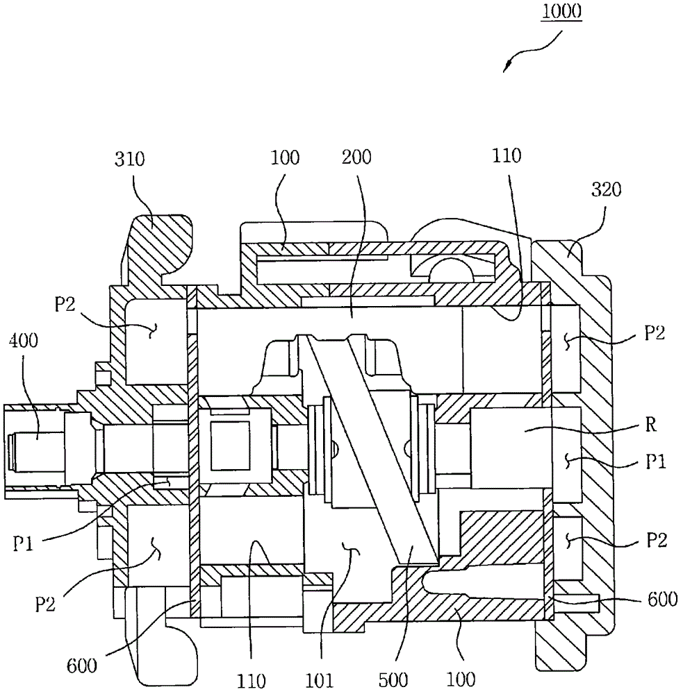
[0048] Such as Figure 3 to Figure 7 As shown in , the swash plate compressor 1000 according to the present invention includes: a cylinder block 100, which has a plurality of cylinder bores 110; a plurality of pistons 200, which are reciprocally accommodated in the cylinder bores 110 of the cylinder block 100; A front housing 310 and a rear housing 320, which are hermetically connected to the front and rear sides of the cylinder block 100, respectively; a drive shaft 400, which is installed to be rotatable relative to the front housing 310 and the cylinder block 100; installed to move in conjunction with the drive shaft 400 and the piston 200; a pair of valve discs 600 interposed between the cylinder block 100 and the front casing 310 and the rear casing 320, respectively.

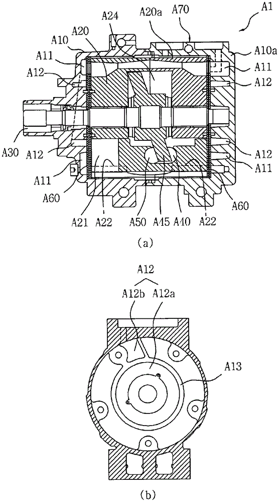
[0049] The above setting of the swash plate compressor and figure 1 and figure 2 The settings of the conventional technology are the same, therefore, the same settings will not be repeated but only diff...

Embodiment 2

[0077] In the following, reference will be made to Figure 8 to Figure 11 A second embodiment of the present invention is described in detail.

[0078] The swash plate type compressor 1000 according to the present invention includes: a cylinder block 100 having a plurality of cylinder bores 110; a plurality of pistons 200 reciprocally housed in the cylinder bores 110 of the cylinder block 100; a front housing 310 and rear housing 320, which is hermetically connected to the front and rear sides of the cylinder block 100, respectively; the drive shaft 400, which is installed to be rotatable relative to the front housing 310 and the cylinder block 100; the swash plate 500, which is installed to combine the drive The shaft 400 and the piston 200 are moved; a pair of valve discs 600 are respectively interposed between the cylinder block 100 and the front housing 310 and the rear housing 320 .

[0079] Likewise, since the above setup of the swash plate compressor is the same as fi...


PUM


Abstract

The present invention relates to a swash plate compressor with a rotary valve which can effectively siphon a coolant into a swash plate chamber through a cylinder block. The swash plate compressor comprises a housing connected to the cylinder block which has a plurality of cylinder bores, pistons which are accommodated and reciprocate in the respective cylinder bores, a drive shaft which is installed to rotate with respect to the housing and the cylinder block, a swash plate which is installed to be rotated by the drive shaft and interlock with the pistons, a valve plate which is interposed between the housing and the cylinder block, and the rotary valve which is formed to rotate along with the drive shaft and installed to roll in a joint hole formed in the cylinder block. A coolant outlet is formed on the exterior of the rotary valve, connection holes connected to the respective cylinder bores are formed on the interior of the joint hole which abuts against the exterior of the rotary valve, and a coolant inlet groove is formed to penetrate the swash plate chamber through to the housing. Therefore, loss caused by coolant inlet resistance can be remarkably reduced by siphoning coolant regardless of the torque of the drive shaft rotating at high speed.

Description

technical field [0001] The present invention relates to a swash plate type compressor having a rotary valve, and more particularly to a swash plate type compressor having a rotary valve capable of effectively sucking refrigerant introduced into a crankshaft chamber through a cylinder block . Background technique [0002] In general, an air conditioning system for a vehicle is adapted so that the interior temperature of the vehicle is lower than the exterior temperature, and it includes a compressor, a condenser, and an evaporator to form a refrigerant cycle. [0003] Such compressors are arranged to compress and supply refrigerant and are driven by the engine or power from the engine. [0004] In a swash plate compressor of the reciprocating compressor type, a disc-shaped swash plate is mounted on a drive shaft to which power from the engine is transmitted so that the roll angle of the swash plate can be varied as the drive shaft rotates Or fixed, and installed around the ...

Claims


Application Information

Patent Timeline
Patent Type & Authority Patents(China)
IPC IPC(8): F04B25/04F04B27/08
CPCF04B49/03F04B27/0878F04B27/1018F04B27/1045F04B27/1081F04B39/1066F05B2210/12F05B2210/14F05B2280/4003Y10S417/00
Inventor 李权熙朴成钧金基范李建祜
Owner DOOWON TECHN COLLEGE
Why Eureka
Try Eureka