Low temperature atomization lubrication cooling system

An atomization lubrication and cooling system technology, which is applied to metal processing machinery parts, maintenance and safety accessories, metal processing equipment, etc., can solve the problems of inability to reduce the cutting heat of the tool, burning the tool and overheating the workpiece, large lubricating oil particles, etc. problem, to achieve the effect of strong cooling performance, uniform lubrication, and small size

Inactive Publication Date: 2011-12-14
成都三洪高科科技有限公司
View PDF6 Cites 22 Cited by
  • Summary
  • Abstract
  • Description
  • Claims
  • Application Information

AI Technical Summary

Problems solved by technology

Although the micro-lubrication system reduces the processing cost and environmental pollution, the special oil injection device uses high-speed flowing compressed air to spray vegetable cutting oil on the cutting edge and the parts that will generate friction, between the tool and the workpiece. Form a layer of oil film, each nozzle consumes 80ml~200ml in 1 hour
In addition, the high-speed compressed air blows away part of the heat and debris. The high-speed compressed air blows out the lubricating oil without atomization. The sprayed lubricating oil particles are large and uneven, and the oil accumulation at the nozzle is serious, and the lubricating effect is not good. It is not ideal, and the heat transfer rate of oil is 2.5 times lower than that of water. Large particles of oil droplets and normal temperature compressed air cannot reduce the heat generated during the cutting process of the tool, which may easily cause overheating and wear of the tool, burning of the tool and overheating of the workpiece out of shape

Method used


Image

  • Low temperature atomization lubrication cooling system
  • Low temperature atomization lubrication cooling system
  • Low temperature atomization lubrication cooling system

Examples


Embodiment Construction

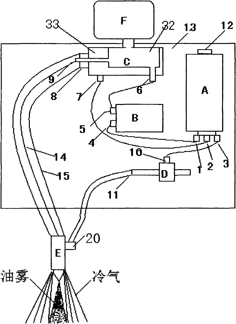
[0014] refer to figure 1 . In the low-temperature atomization lubrication cooling system provided by the present invention, there is an installation box 13 . The lubricating oil cup F is fixedly connected above the installation box 13 . The lubricating oil cup F is connected to the shunt pump C arranged in the box body 13 through a communication joint. The supercharger A connected with the compressed air source is fixedly connected to one side of the installation box 13 . The external compressed air source enters the supercharger A through the compressed air source inlet 12 connected to the upper end of the supercharger A. Between the supercharger A and the liquid-feeding lubricating oil cup F, a shunt pump C communicated through the supercharger A is provided. The supercharger A communicates with the rectifying atomizing nozzle E through the split flow pump C, and communicates with the oil cup F and the pulser B at the same time. Below the supercharger A, three-component...


PUM


Abstract

The invention provides a low-temperature atomized lubrication cooling system, aiming at providing a lubrication cooling system which can be used for reducing the using amount of a cooling lubricant and effectively improving the cooling lubrication effect and has small size and no oil deposit at a spray nozzle. The low-temperature atomized lubrication cooling system is characterized in that: a diverter pump and a pulser which are communicated with a rectifying and atomizing nozzle and an oil cup are arranged between a pressurizer and the oil cup; three groups of diverter air nozzles are arranged on the pressurizer, wherein an intermitted airflow is formed at one group of diverter air nozzles through the pulser and enters the diverter pump, and the other tow groups of diverter air nozzles are respective and directly communicated into an interlayer port of the diverter pump and an air inlet nozzle of a vortex generator; and a double-core outlet which is communicated with an interlayer ofthe diverter pump and a main cavity of the diverter pump is also arranged on the output end of the diverter pump, and vertex cold air which is generated at the double-core outlet through a double-core air pipe and a vertex generator that are connected flows into the rectifying and atomizing nozzle. According to the invention, the problems of large lubrication cooling quantity and pollution causedby waste oil discharge in the traditional machining operation are solved, oil is saved, and the using amount of cutting fluid for atomizing and lubricating is only 0.03-0.2L/h generally.

Description

technical field [0001] The invention relates to a cooling system mainly used for lubricating and cooling cutting tools in the machining process. More specifically, the present invention relates to a low-temperature atomized lubrication cooling system used in machining processes. Background technique [0002] At present, in the metal processing cooling system, the most common method of using cutting fluid is the overflow method. The overflow method system uses a low-pressure pump to drive the cutting fluid into the pipeline, and flows out from the nozzle through the valve. The nozzle is installed close to the cutting area. The cutting fluid flows through the cutting area and then flows to different parts of the machine tool, and then gathers in the oil collection In the pan, it flows back from the oil collecting pan to the cutting fluid tank for recycling. Therefore, the cutting fluid tank should have enough volume to allow the cutting fluid to have time to cool and settle ...

Claims


Application Information

Patent Timeline
Patent Type & Authority Applications(China)
IPC IPC(8): B23Q11/10
Inventor 康伟
Owner 成都三洪高科科技有限公司
Why Eureka
Try Eureka