A mipm type internal field emission cathode

A field emission cathode and bottom electrode technology, applied in the field of vacuum electronics and materials science, can solve the problems of low emission efficiency and low emission current density

Inactive Publication Date: 2011-12-14
SICHUAN UNIV
View PDF6 Cites 17 Cited by
  • Summary
  • Abstract
  • Description
  • Claims
  • Application Information

AI Technical Summary

Problems solved by technology

[0006] A technical problem to be solved by the present invention is that the emission efficiency of the existing MISM type internal field emission cathode is not high, and the emission current density is low.

Method used


Image

  • A mipm type internal field emission cathode

Examples


Embodiment 1

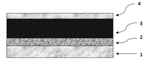
[0013] refer to figure 1 , the material of the bottom electrode 1 is gold with a thickness of 500 nm; the material of the insulating layer 2 is SiO 2 , with a thickness of 100 nm; the material of the electron storage and transport layer 3 is porous silicon with a thickness of 40 μm, its average conductivity is 0.01 Ω, the average porosity is 50%, and the average pore diameter is 30 nm; the material of the top electrode 4 is gold , with a thickness of 15 nm. at 10 -5 Under torr pressure, the measured emission efficiency is 1.5%, and the beam decays by 1% after 20 hours of continuous operation.

Embodiment 2

[0015] refer to figure 1 , the material 1 of the bottom electrode is chromium with a thickness of 200 nm; the material of the insulating layer 2 is HfO 2 , with a thickness of 300 nm; the material of the electron storage and transport layer 3 is porous silicon, with a thickness of 40 μm, an average conductivity of 0.01 Ω, an average porosity of 50%, and an average pore diameter of 50 nm; the material of the top electrode 4 is Ag , with a thickness of 10 nm. at 10 -5 Under torr pressure, the measured emission efficiency is 1.5%, and the beam decays by 1% after 20 hours of continuous operation.

Embodiment 3

[0017] refer to figure 1 , the material of the bottom electrode 1 is Ag, and the thickness is 200 nm; the material of the insulating layer 2 is Ta 2 o 5 , with a thickness of 400 nm; the material of the electron storage and transport layer 3 is porous silicon, with a thickness of 30 μm, an average conductivity of 0.01 Ω, an average porosity of 50%, and an average pore diameter of 30 nm; the material of the top electrode 4 is ZrN , with a thickness of 8 nm. at 10 -5 Under torr pressure, the measured emission efficiency is 1.3%, and the beam decays by 1% after 20 hours of continuous operation.


PUM


Abstract

A cathode of the invention belongs to the field of vacuum electronics and the materials science, and in particular relates to an MIPM (multum in parvo mapping)-type internal field emitting cathode. The MIPM-type internal field emitting cathode is composed of a bottom electrode layer, an insulating layer, an electronic storage transmission layer and a top electrode layer; the emitting cathode is mainly characterized in that the electronic storage transmission layer adopts a porous silicon film material. In an alternating current AC driving mode, a functional layer not only can transport electrons, but also can store the electrons so as to improve the emitting efficiency. Compared with the prior art, the MIPM-type internal field emitting cathode has the advantages of great emitting current and good stability; and due to the strong environment adaptability, the cathode not only can work in the gas, but also can work in the liquid.

Description

technical field [0001] The invention belongs to the field of vacuum electronics and material science, in particular to an MIPM type internal field emission cathode. Background technique [0002] There are three types of field electron emission: one is external field emission, the other is internal field emission, and the third is transverse field emission. [0003] External field emission cathodes are made of metal or semiconductor cones, nanotubes, nanowires, etc. The principle is to use an external strong electric field to suppress the surface barrier, reduce the highest point of the barrier, and narrow the width of the barrier. When the width of the barrier on the surface of the cold cathode is compressed by the electric field to be comparable to the wavelength of electrons, a large number of electrons escape through the surface barrier due to the tunneling effect of electrons. The principle of lateral field emission is to use the conduction current of discontinuous film...

Claims


Application Information

Patent Timeline
Patent Type & Authority Applications(China)
IPC IPC(8): H01J1/312
Inventor 邹宇展长勇林黎蔚任丁刘波黄宁康肖婷
Owner SICHUAN UNIV
Why Eureka
Try Eureka