A Circularly Polarized Microstrip Antenna Using a Wave-shaped Slot Structure

A microstrip antenna, wave-shaped technology, applied in the direction of antenna, radiating element structure, electrical components, etc., can solve the problems of complex curved structure combination research, low utilization rate of metal patch surface, unfavorable antenna matching, etc., to achieve expansion The effect of application occasion, simple structure and low processing cost

A microstrip antenna, wave-shaped technology, applied in the direction of antenna, radiating element structure, electrical components, etc., can solve the problems of complex curved structure combination research, low utilization rate of metal patch surface, unfavorable antenna matching, etc., to achieve expansion The effect of application occasion, simple structure and low processing cost

CN102280701AActive Publication Date: 2011-12-14BEIHANG UNIV

Image

  • A Circularly Polarized Microstrip Antenna Using a Wave-shaped Slot Structure
  • A Circularly Polarized Microstrip Antenna Using a Wave-shaped Slot Structure
  • A Circularly Polarized Microstrip Antenna Using a Wave-shaped Slot Structure

Examples


Embodiment Construction

[0035] The present invention will be described in detail below in conjunction with the accompanying drawings and specific embodiments, but not as a limitation of the present invention.

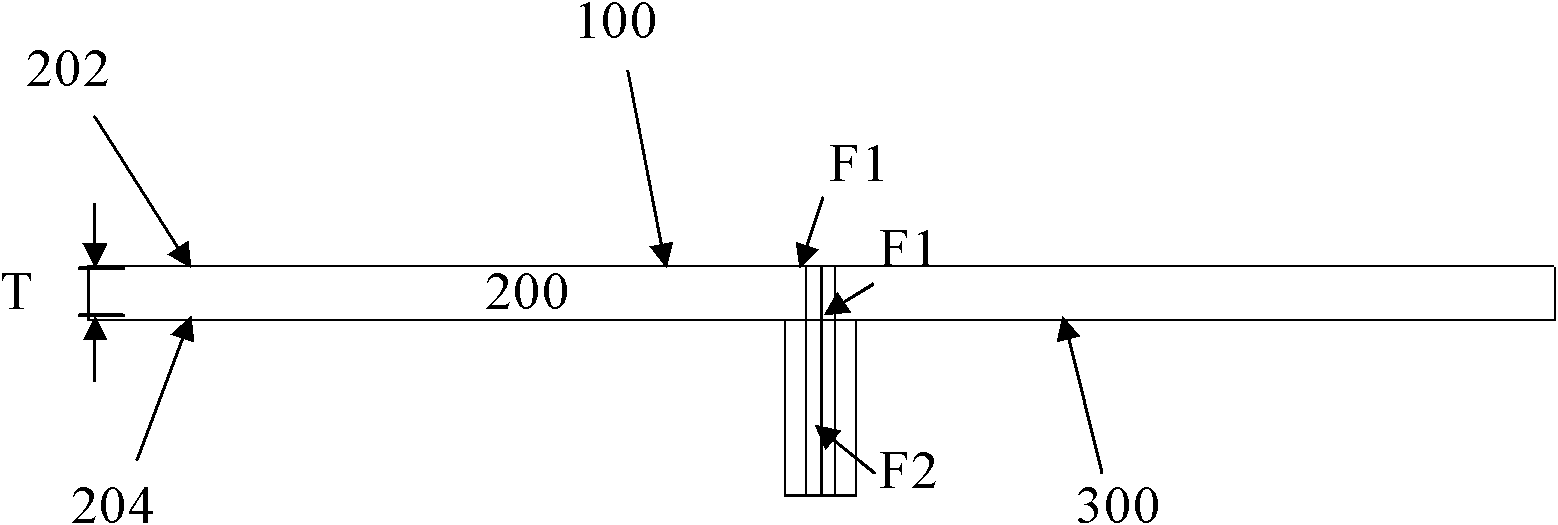
[0036] Please refer to Figure 1A and Figure 1B , which is a schematic diagram of a side view and a top view of a microstrip antenna in a preferred embodiment of the present invention.

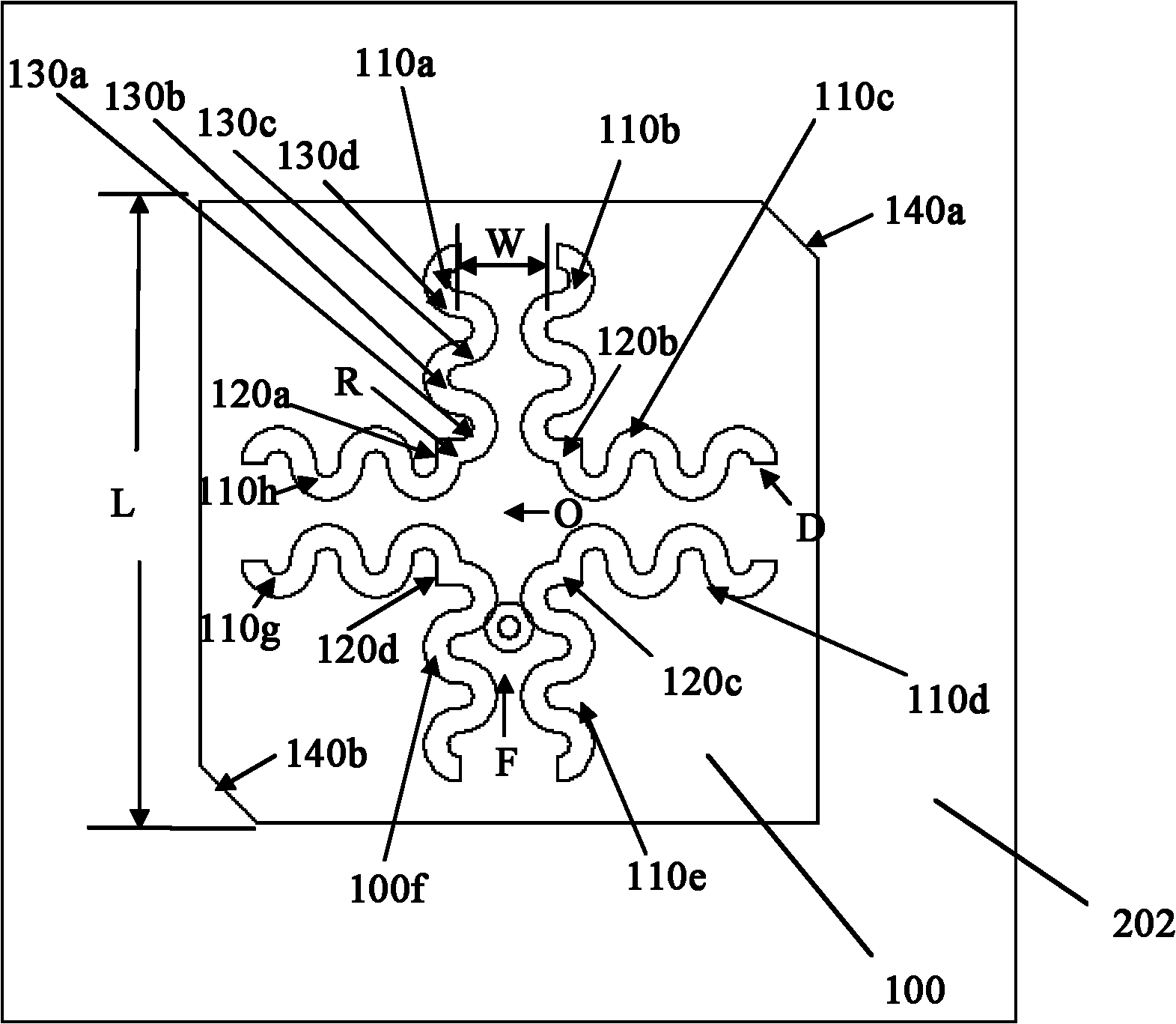
[0037] Such as Figure 1AAs shown, the metal patch 100 has a groove structure, and the groove structure exposes part of the first surface 202 of the dielectric substrate 200 . The slot structure is composed of eight wavy grooves 110a to 110h and four square connecting grooves 120a to 120d; the first wavy groove 110a is composed of first semicircle to fourth semicircle 130a to 130d, wherein the first semicircle 130a It is connected end to end with the second semicircle 130b, the second semicircle 130b is connected end to end with the third semicircle 130c, and the third semicircle 130c is connected end to end...


PUM


Abstract

The invention relates to a circularly polarized micro-strip antenna adopting a wave-shaped groove structure, which is used for reducing the size of the antenna, expanding application occasions, reducing the processing cost and meeting the demands of the antenna. The micro-strip antenna adopts a coaxial feed structure and comprises a dielectric substrate, a metal floor and a metal patch with a groove structure, wherein the metal patch is positioned on the upper surface of the dielectric substrate, the groove structure comprises eight wave-shaped grooves and four square connecting grooves, two wave-shaped grooves which are in mutual mirroring and in one group are selected from the eight wave-shaped grooves as the standard, the other six wave-shaped grooves can be obtained by rotating the group of wave-shaped grooves which are in the mutual mirroring around the central position of the metal patch 90 degrees, 180 degrees and 270 degrees, and the four square connecting grooves are used for connecting the two wave-shaped grooves which are adjacent but not in mirroring. The circularly polarized micro-strip antenna has the advantages of reduced size and lowered processing cost.

Description

technical field [0001] The invention relates to a microstrip antenna with a slot structure, in particular to a circularly polarized microstrip antenna with a wave-shaped slot structure. Background technique [0002] With the vigorous development of communication technology, various communication products and technologies have sprung up like mushrooms after rain. The technology of integrated circuits is becoming more and more mature, so that the volume of products is gradually thinner and smaller. For the antenna used to transmit and receive signals in communication products, its size is directly related to whether the communication product can achieve the goal of being thin, light and small. [0003] The antenna is a component used to transmit or receive electromagnetic waves. Generally, the characteristics of the antenna can be obtained from parameters such as operating frequency, radiation pattern (Radiation Pattern), reflection coefficient (Return Loss) and antenna gain ...

Claims


Application Information

Patent Timeline
14 Dec 2011
Publication
CN102280701A
IPC
H01Q1/38; H01Q13/08
Inventors
张岩; 石庆琳