
External cavity electro-optic tunable laser

A laser and electro-optical technology, applied in the field of lasers, can solve the problems of poor reliability, laser vibration sensitivity, and laser stability deterioration, and achieve the effects of reducing vibration impact, fast response, and improving work stability.

Active Publication Date: 2011-12-14
瑞泰(威海)电子科技有限公司
View PDF4 Cites 10 Cited by
  • Summary
  • Abstract
  • Description
  • Claims
  • Application Information

AI Technical Summary

Problems solved by technology

The international communication standard stipulates that C-Band covers 100 channels at intervals of 50Ghz from 1530nm to 1570nm. As an adjustable laser for communication light sources, the existing invention includes changing the optical frequency of the laser by changing the cavity length of the DFB by heating. This invention The frequency adjustment time of the adjustable laser is more than a few seconds; some inventions add a grating in the laser cavity and use a micro-motor to change the angle of the grating to select the output frequency. The problem with this invention is that the laser is very sensitive to the vibration of the environment. , Poor reliability; Another invention is to add an acousto-optic device in the laser cavity to change the optical frequency of the laser. The problem of this invention is that the heat generated by the sound wave makes the stability of the laser worse.

Method used


Image

  • External cavity electro-optic tunable laser
  • External cavity electro-optic tunable laser
  • External cavity electro-optic tunable laser

Examples


Embodiment

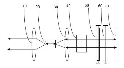
[0026] Such as figure 1 As shown, the external cavity electro-optic tunable laser described in this embodiment is a laser with a broadband film arranged at the front end of the high reflection mirror 70, which includes a collimator lens 10 and a collimator lens 30, and is arranged between the two collimator lenses. The optical gain medium 20, the electro-optic tunable filter located at the rear end of the collimator lens 30, the electro-optic tunable liquid crystal phase compensator 60 and the high reflection mirror 70, also include a broadband film and fixed Fabry- Perot cavity 40, the fixed Fabry-Perot cavity is arranged at the front end of the electro-optic tunable filter, and the high reflection mirror 70 is arranged at the end of the electro-optic tunable liquid crystal phase compensator 60 At the rear end, the bandwidth of the broadband film mode is less than the period interval of the electro-optic tunable filter, and the bandwidth of the electro-optic tunable filter is...


PUM


Abstract

The invention provides an outer cavity type electrooptically tuned laser device, wherein an adopted electrooptically tuned filter adopts a liquid crystal Fabry-Perot cavity with very short cavity length and can ensure that only one mode of the fixed Fabry-Perot cavity of the filter is selected within one period interval, a broadband film is used for filtering periodic multiple waves generated by the fixed Fabry-Perot cavity and only reflecting wavelength of one peak to an optical resonant cavity, then one peak of a longitudinal mode of the optical resonant cavity can be adjusted to a main peak of the electrooptically tuned filter through an electrooptically tuned liquid crystal phase compensator, then single mold output of laser can be ensured, and the stability and reliability of the output of the laser can be improved.

Description

technical field [0001] The invention relates to the technical fields of optical instruments and optical fiber communication, and specifically designs an external-cavity electro-optic adjustable laser. Background technique [0002] In the era of optical communication, lasers are used as the carrier of digital signals. Each optical frequency of the laser corresponds to each channel of communication. Each optical fiber can accommodate multiple communication channels, that is, laser carriers of multiple frequencies. The frequency of the laser will need to be changed dynamically as the network traffic changes. The international communication standard stipulates that C-Band covers 100 channels at intervals of 50Ghz from 1530nm to 1570nm. As an adjustable laser for communication light sources, the existing invention includes changing the optical frequency of the laser by changing the cavity length of the DFB by heating. This invention The frequency adjustment time of the adjustabl...

Claims


Application Information

Patent Timeline
Patent Type & Authority Applications(China)
IPC IPC(8): H01S3/137
Inventor 余模智
Owner 瑞泰(威海)电子科技有限公司
Learn More