Differential bevel gear and rack compound underactuated robot finger device

A technology of robot fingers and bevel gears, applied in the field of humanoid robot hands, can solve the problems of difficult end pinching and grasping effects, lack of self-adaptability, large deformation of multiple spring parts, etc., and achieves convenient assembly and maintenance and simple structure , the effect of small energy loss

Inactive Publication Date: 2011-12-21
TSINGHUA UNIV
View PDF9 Cites 13 Cited by
  • Summary
  • Abstract
  • Description
  • Claims
  • Application Information

AI Technical Summary

Problems solved by technology

[0007] 2) The grasping method of the under-actuated hand is mainly the gripping method, and it is difficult to achieve a better grasping effect of the terminal pinch; it cannot achieve the fisting action similar to a human hand when there is no object grasping; it is also difficult to achieve terminal finger pinching When holding an object, the joints are in a natural bending state
[0008] 3) When the under-actuated hand grasps an object, the first finger segment needs to exert sufficient force on the object to trigger the second joint to pull the spring to deform and bend, which will lead to an unstable grasping phenomenon in which the grasping force squeezes the object away. Even if the object is grasped, it may cause the first finger segment to grasp the object too much and damage the object
The disadvantage of coupled fingers is that there is no adaptability to different objects when grasping objects
[0015] The device can realize compound under-actuated grasping, but the disadvantage is that the mechanism is complex and difficult to install and maintain; the number of spring parts is too large, and the contradiction between the coupling transmission mechanism and the self-adaptive transmission mechanism is often adjusted by using the spring part decoupling, which often makes multiple spring parts High deformation, resulting in excessive and unnecessary energy loss

Method used


Image

  • Differential bevel gear and rack compound underactuated robot finger device
  • Differential bevel gear and rack compound underactuated robot finger device
  • Differential bevel gear and rack compound underactuated robot finger device

Examples


Embodiment Construction

[0035] The specific structure and working principle of the present invention will be further described in detail below in conjunction with the accompanying drawings and embodiments.

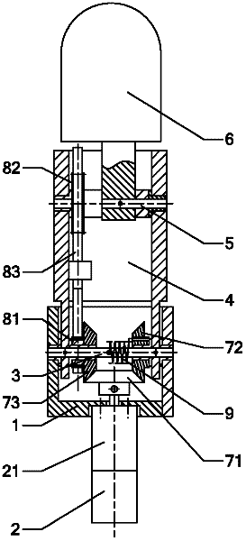
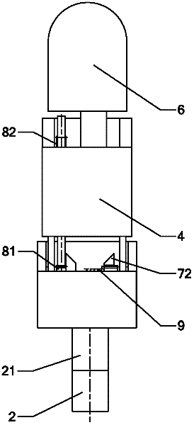
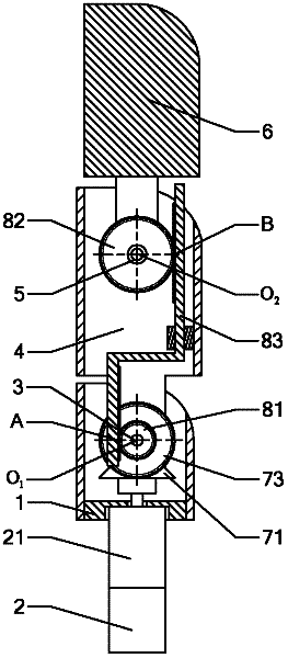
[0036] An example of the differential bevel rack and pinion compound underactuated robot finger device of the present invention, as Figure 1 to Figure 5As shown, it includes a base 1, a motor 2, a reducer 21, a proximal joint shaft 3, a middle finger segment 4, a distal joint shaft 5 and an end finger segment 6; the motor 2 and the reducer 21 are fixed on the base 1 Above, the output shaft of the motor 2 is connected with the input shaft of the reducer 21; the proximal joint shaft 3 is movably sleeved in the base 1, and the distal joint shaft 5 is movably sleeved in the middle finger segment 4, and the middle The finger segment 4 is fixed on the proximal joint axis 3; the terminal finger segment 6 is fixed on the distal joint axis 5, and the proximal joint axis 3 is parallel to the distal joint ...


PUM


Abstract

The differential bevel gear and rack type compound underactuated robot finger device belongs to the technical field of humanoid robot hand, including base, motor, reducer, proximal joint shaft, middle finger segment, distal joint shaft, end finger segment, rack and Spring parts. The device of the present invention adopts a single motor, multi-axis and multi-channel transmission mechanisms with different transmission ratios and spring parts to comprehensively realize the compound under-actuated grasping effect: the fingers are first coupled and rotated to grasp the object and then adaptively grasp the object; the grasping process Anthropomorphic, dexterous, stable grasping objects, can automatically adapt to grasping objects of different sizes and shapes, low requirements on the control system, easy to operate; at the same time, the structure is simple and compact, the energy loss is small, the transmission efficiency is high, the cost is low, and the assembly and maintenance are easy. Convenient, and the shape is similar to human fingers, suitable for humanoid robot hands.

Description

technical field [0001] The invention belongs to the technical field of humanoid robot hands, and in particular relates to a structural design of a differential bevel gear rack type composite underactuated robot finger device. Background technique [0002] The hand is a very important organ for humans. In the field of humanoid robots, it is of great significance to enhance the function of the robot hand. On the one hand, by increasing the number of joints and the number of drives, the movement of the manipulator can be made more diverse and precise, but at the same time, this will make the mechanism complex and cumbersome; The accuracy of the movement is negatively affected. At the same time, the robot hand is required to be compact and flexible with sufficient grasping force. There are still many technical problems in this field. [0003] An underactuated mechanism is one in which the number of actuators is less than the number of joint degrees of freedom. Many humanoid ...

Claims


Application Information

Patent Timeline
Patent Type & Authority Applications(China)
IPC IPC(8): B25J15/08
CPCB25J15/0009
Inventor 张文增王智
Owner TSINGHUA UNIV
Why Eureka
Try Eureka