DC and swirl combined burner

A burner and axial flow technology, which is applied in the direction of burners, lighting and heating equipment, etc., can solve the problems of poor separation between swirling air and direct current air, high consumption of pulverized coal and fuel oil, and large consumption of primary direct current air, etc. Achieve the effect of reducing spare parts consumption, reducing maintenance rate, and benefiting environmental protection

Inactive Publication Date: 2011-12-21
徐道芹
View PDF11 Cites 2 Cited by
  • Summary
  • Abstract
  • Description
  • Claims
  • Application Information

AI Technical Summary

Problems solved by technology

Its defect is: the area of ​​the nozzle is small, the inner swirl wind and the outer dc wind are very close, and there is no separation, the inner swirl wind interferes with the movement direction of the outer dc wind, making the dc wind move closer to the swirl wind, resulting in a The consumption is large and the waste is high; the separation between the swirling air and the direct air is not good, the pulverized coal disperses slowly and the effect is poor, the black fire head is long, the combustion is insufficient, and the pulverized coal and fuel consumption are high; In the center line of the coal pipe, the coal powder directly collides with the central air duct in the middle

Method used


Image

  • DC and swirl combined burner
  • DC and swirl combined burner
  • DC and swirl combined burner

Examples


Embodiment Construction

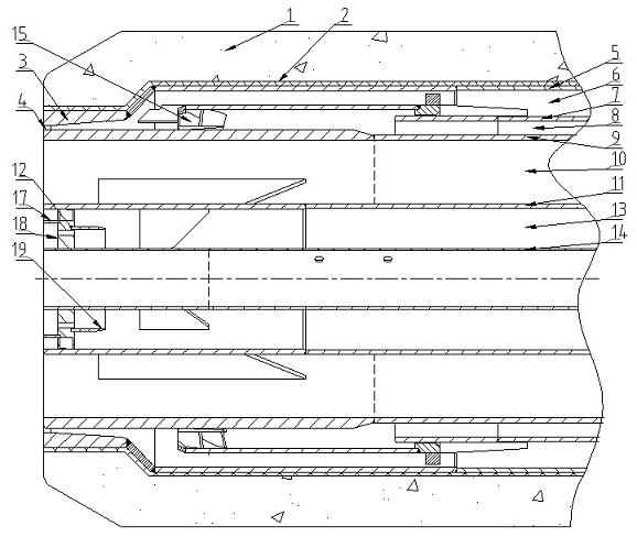
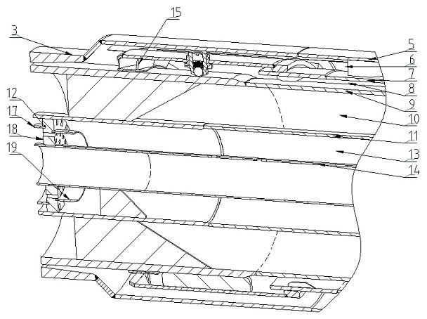
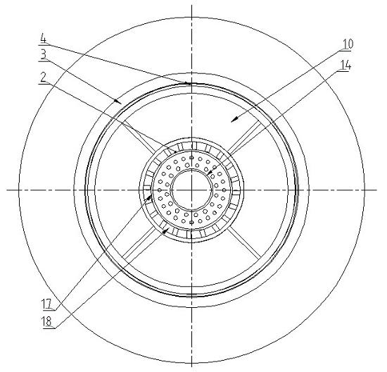
[0023] Depend on figure 1 , figure 2 , image 3 , Figure 9 It can be seen that the combined direct current and swirl flow burners are coaxially arranged by refractory sheath 1, asbestos layer 2, axial flow duct 5, radial duct 7, pulverized coal duct 9, and central mixing duct 11. It is set on the fuel pipe 14, and supports are provided between the pipes of each layer. The axial flow duct and the radial duct form the axial duct 6, and the radial duct and the pulverized coal duct form the radial duct 8. The radial air channel and the front part of the axial flow channel are connected together to form a mixed air channel 4, the radial air channel is provided with a swirl plate 15, the nozzle ring 3 is connected with the axial flow duct 5, and is fixed on the front end of the axial flow duct. The mixing isolation plate 12 is fixed on the central mixing air duct 11 and placed at the front end of the central mixing air duct. The pulverized coal air duct 9 and the central mixing...


PUM


Abstract

The direct-flow and swirl-flow combustible burner relates to a burner that combusts liquid fuel and powder fuel at the same time. The characteristic is that the axial flow air channel is composed of axial flow air duct and radial air duct, the radial air channel is composed of radial air duct and pulverized coal air duct, and the axial flow air channel and radial air channel are connected together to form a mixed air channel. A nozzle ring is provided at the opening of the mixing air channel; the pulverized coal air pipe and the central mixing air pipe form the pulverized coal air channel; on the coal pipe. The advantages are: novel and compact structure, easy to manufacture, and reliable use; it solves the problem of mutual interference between direct air and swirling air, increases the degree of separation, quickly disperses coal powder, shortens the length of the black fire head, and reduces the amount of primary air and NOx emissions ; The pulverized coal is evenly distributed, and the combustion is sufficient, which improves the combustion efficiency, saves energy and reduces consumption; reduces pipeline wear, prolongs service life, and reduces spare parts consumption, which is beneficial to production.

Description

technical field [0001] The invention belongs to a burner, in particular to a burner which burns liquid fuel and powder fuel simultaneously. Background technique [0002] At present, industrial kilns mostly use four-channel or multi-channel burners. A "secondary enhanced swirl cement burner" (CN201434389Y) disclosed by the China Intellectual Property Office. The center of the burner is a fuel pipe, and the fuel pipe has layers of pipes that are coaxially sleeved from the inside to the outside: DC cooling air channel, secondary swirling air channel, coal conveying air channel, main swirling air channel, and jetting air channel; there are multiple points of support between the pipe layers, the direct current cooling air channel has an orifice plate, and the secondary swirling air channel has a swirling oblique orifice plate. Its defect is: the area of ​​the nozzle is small, the inner swirl wind and the outer dc wind are very close, and there is no separation, the inner swirl ...

Claims


Application Information

Patent Timeline
IPC IPC(8): F23D17/00
Inventor 徐道芹
Owner 徐道芹
Why Eureka
Try Eureka