A vacuum loading device and its test method

A technology of loading equipment and vacuuming, applied in the direction of applying stable tension/pressure to test the strength of materials, measuring devices, instruments, etc., can solve problems such as the inability to meet the compression stability test of the upper wall plate of the central wing, and ensure reliability. and stability effects

Active Publication Date: 2011-12-21
CHINA AIRPLANT STRENGTH RES INST
View PDF6 Cites 12 Cited by
  • Summary
  • Abstract
  • Description
  • Claims
  • Application Information

AI Technical Summary

Problems solved by technology

The technology of this test cannot meet the requirements of the compression stability test of the upper panel of the central wing becau

Method used


Image

  • A vacuum loading device and its test method
  • A vacuum loading device and its test method
  • A vacuum loading device and its test method

Examples


Embodiment Construction

[0029] The present invention will be further described in detail below through specific embodiments:

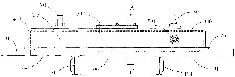
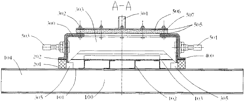
[0030] See also figure 2 , image 3 with Figure 4 ,among them, figure 2 It is a schematic structural diagram of a preferred embodiment of the vacuum loading equipment of the present invention, image 3 Yes figure 2 A-A section view, Figure 4 Yes figure 2 Top view. The vacuum loading equipment is mainly a vacuum box assembled on the upper wall of the center wing, which includes a rubber block 201, a sealing gasket 202, a support box 300, a sealing box 400, a cushion block 305, a rubber ring 505, a plexiglass plate 506, Steel pressing ring 507, sensor interface 501, outlet 502, air extraction interface 503 and air intake interface 504.

[0031] Among them, two rectangular rubber blocks 201 (40mm×47.5mm) are pasted on the edge of the skin 101 on one side of the wall truss, which are the key parts of the vacuum loading equipment. The rubber block 201 is flush with the bosses 10...


PUM


Abstract

The invention belongs to an airtight loading technology and relates to airtight load test loading equipment and an airtight load test loading method for a reinforced wall plate of an airplane. Vacuumizing loading equipment comprises a rubber block, a sealing gasket, a supporting box and a sealing box, wherein the rubber block is adhered to a skin edge on one surface of a long girder of the wall plate and flushed with bosses at two ends of the wall plate; the sealing block is adhered to the rubber block and a floor beam; the supporting box is adhered to the inside of the rubber block; a fixing bolt which is used for fixing the supporting box is arranged at the top of the supporting box; the sealing box is in adhered connection with the rubber block and sleeve outside the supporting box; and a hole and an opening, which correspond to the supporting box, are reserved in the sealing box. The invention has the advantages that: during test of the supporting box, the skin of the wall plate cannot be deformed through isolation of the rubber block; because the own rigidity of the rubber block is quite low, requirements of only application of an airtight load without change of boundary conditions of the wall plate can be met; and the reliability and stability of loading test and the accuracy of a test result are guaranteed.

Description

Technical field [0001] The invention belongs to the airtight load loading technology, and relates to an airtight load test loading equipment of an aircraft stiffened wall panel and a loading method thereof. Background technique [0002] Aircraft load loading test is an important subject of aircraft strength testing, especially when testing the strength of the aircraft center wing, load loading test is necessary. See figure 1 , Which is a schematic diagram of the structure of the upper wall panel of the central wing and its load in the prior art. The upper wall panel 100 of the center wing of a certain type of civil aircraft includes a skin 101, a long stringer 102, a boss 103 and a floor beam 104. Among them, the skin 101 is arranged on the long truss 102 to form a wall panel structure to bear the compressive load 105 and the pressurized load 106 of the passenger cabin, and the upper and lower sides of the skin 101 are respectively provided with a boss 103 and a floor beam 104. ...

Claims


Application Information

Patent Timeline
IPC IPC(8): G01N3/02G01N3/12
Inventor 王俊安
Owner CHINA AIRPLANT STRENGTH RES INST
Why Eureka
Try Eureka