Airflow Angular Velocity Sensor

An angular velocity sensor and airflow-type technology, which is applied to devices that use fluids, etc., can solve the problems of unstable sensor output, poor repeatability, and large volume, and achieve the effect of simplifying the structure, reducing loss, and improving resolution.

Inactive Publication Date: 2011-12-21
BEIJING INFORMATION SCI & TECH UNIV
View PDF3 Cites 16 Cited by
  • Summary
  • Abstract
  • Description
  • Claims
  • Application Information

AI Technical Summary

Problems solved by technology

Therefore, it has the disadvantages of large volume, high cost, and strong cross-coupling betw

Method used


Image

  • Airflow Angular Velocity Sensor
  • Airflow Angular Velocity Sensor
  • Airflow Angular Velocity Sensor

Examples


Embodiment 1

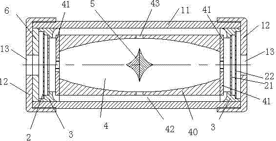
[0027] Such as figure 1 As shown in , the airflow angular velocity sensor in the present invention includes: a housing 1, a piezoelectric pump 2, a piezoelectric pump seat 3, a test cavity 4, a sensitive element 5, a disc spring 6 and a signal processing circuit (not shown in the figure), The housing 1 is composed of a side wall 11 and a base 12 arranged at both ends of the side wall. The side wall 11 can be in the shape of a thin-walled cylinder or in other shapes. The two bases 12 are also provided with power outlet outlets 13, and the two bases 12 are provided with power outlet outlets 13 for the convenience of the installation of the angular velocity sensor, so that the setting position of the angular velocity sensor is not limited by the position of the external power supply. When working, only one of the two outlets 13 is used, and the other is closed. After the power supply and the wires are drawn out from the outlet 13, the outlet 13 used will also be closed, so that ...

Embodiment 2

[0035] Such as Figure 8 As shown in , the structure of the airflow angular velocity sensor in this embodiment is basically the same as that in Embodiment 1, the difference is that the axial cross-sectional shape of the test chamber structure is a rectangle with rounded corners. Compared with the trumpet-shaped design in Example 1, this design increases the volume of the test cavity, expands the space for the gas to circulate inside the cavity, and suppresses the divergence of the jet column. Due to the added design of circular arc chamfering, it reduces the direct collision between the air flow and the four corners of the chamber compared with the rectangular section design of the test chamber in the prior art, and effectively avoids the eddy current phenomenon existing inside the chamber.

[0036] Since the airflow angular velocity sensor adopts zero output, the sensitivity changes greatly with temperature, and the output voltage of the sensor is nonlinear when the input is ...


PUM


Abstract

The invention discloses an airflow type angular velocity transducer, which comprises a testing cavity, a sensitive element arranged at a center position of the testing cavity, two piezoelectric pumps which are symmetrically arranged at two ends of the testing cavity, a gas circulation channel communicated with the testing cavity and the piezoelectric pumps, and a signal processing circuit, wherein the testing cavity is a cavity symmetrical about an axial center and a radial center; two ends of the testing cavity are provided with air inlets; a certain distance is formed between the two piezoelectric pumps and the two ends of the testing cavity; gases in the transducer can circulate in a confined space formed by the testing cavity, the gas circulation channel and the piezoelectric pumps; the sensitive element has a plate frame structure of which the periphery is provided with four groups of thermistor wires; vertical distances between straight lines where the groups of thermistor wiresare positioned and a central position of the sensitive element are the same; opposite two groups of thermistor wires are parallel to each other; adjacent two groups of thermistor wires are vertical to each other; and the center of the sensitive element and the centers of the air inlets are positioned on a center line of the testing cavity.

Description

technical field [0001] The invention relates to an angular velocity sensor, in particular to an air flow angular velocity sensor. Background technique [0002] The airflow angular velocity sensor is a solid-state inertial device that has the function of a gyro without the rotating part of a traditional gyro or the suspension parts of a piezoelectric gyro. The airflow angular velocity sensor uses gas as the sensitive mass, and its mass is extremely small. The airflow sensor is widely used in the field of angular velocity measurement due to its advantages of low cost, short response time, and strong impact resistance. [0003] The air flow angular velocity sensor in the prior art is usually a two-dimensional piezoelectric jet angular velocity sensor, and this air flow angular velocity sensor measures the angular velocity in the x and y directions respectively by setting two sensitive elements. Therefore, it has the disadvantages of large volume, high cost, and strong cross-c...

Claims


Application Information

Patent Timeline
IPC IPC(8): G01P3/28
Inventor 朴林华王星余全刚
Owner BEIJING INFORMATION SCI & TECH UNIV
Why Eureka
Try Eureka