Flow battery, flow battery stack and flow battery system
A technology of liquid flow battery and liquid flow frame, which is applied in the direction of battery electrodes, fuel cells, regenerative fuel cells, etc., and can solve the problems of reducing battery charge and discharge performance and service life, uneven reaction rate and heat of electrodes, etc.
- Summary
- Abstract
- Description
- Claims
- Application Information
AI Technical Summary
Problems solved by technology
Method used
Image

Examples
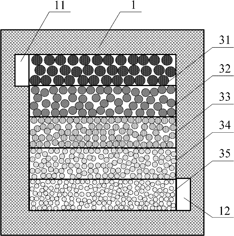
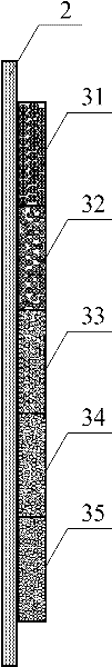
Embodiment 2
[0029] The specific surface area of the electrode 3 of the liquid flow battery of the second embodiment in the flow direction of the electrolyte gradually increases continuously, that is, the contact reaction area continuously increases gradually, thereby offsetting the decrease in the concentration of the reaction substance, thereby effectively It solves the problem that the concentration of the reacting substance in the electrolyte gradually decreases with the progress of the reaction, which leads to the uneven reaction rate and heat generated by the reaction at all parts of the electrode, thereby improving the charging and discharging performance and service life of the battery.
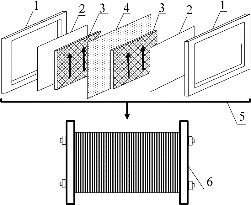
[0030] In embodiment three, the specific surface area of the electrode 3 gradually increases as a continuous increase, such as Figure 5 As shown, the arrow indicates the flow direction of the electrolyte, wherein the electrode 3 and the collector plate 2 form two half-cells, the ion exchange m...
example 1
[0037] Using highly conductive porous graphite felt as the electrode material, five graphite felt electrodes with different specific surface areas but the same dimensions are integrated with the graphite current collector plate by hot pressing. The size of each graphite felt electrode is 40mm×200mm×5mm, forming a 200mm×200mm×5mm graphite felt electrode as a whole, and the specific surface area of the five electrodes increases in the direction of the flow field. The charge-discharge coulombic efficiency of a single cell composed of the graphite felt electrode, the ion-exchange membrane and the current collector plate is 91.2%, the voltage efficiency is 88.9%, and the energy efficiency is 81.1%.
PUM
 Abstract
Description
Claims
Application Information
 - R&D
- Intellectual Property
- Life Sciences
- Materials
- Tech Scout
- Unparalleled Data Quality
- Higher Quality Content
- 60% Fewer Hallucinations
Browse by: Latest US Patents, China's latest patents, Technical Efficacy Thesaurus, Application Domain, Technology Topic, Popular Technical Reports.
© 2025 PatSnap. All rights reserved.Legal|Privacy policy|Modern Slavery Act Transparency Statement|Sitemap|About US| Contact US: help@patsnap.com