Current collector plate of flow battery and flow battery

A liquid flow battery and collector plate technology, which is applied to fuel cell components, regenerative fuel cells, collectors/separators, etc., can solve the problem of uneven electrode reaction rate and reaction heat generation, lower battery charge and discharge performance and Problems such as service life and uneven electrolyte flow, to achieve the effect of reducing polarization, improving service life and smooth flow

Inactive Publication Date: 2011-12-28
中国东方电气集团有限公司
View PDF7 Cites 16 Cited by
  • Summary
  • Abstract
  • Description
  • Claims
  • Application Information

AI Technical Summary

Problems solved by technology

[0009] The purpose of the present invention is to provide a current collecting plate of a liquid flow battery and a liquid flow battery to solve the problem of energy waste and uneven flow of electrolyte caused by the lack of guiding effect of the current collecting plate in the prior art, and the concentration of reacting substances in the electrolyte increases with the The progress of the reaction is gradually reduced, resulting in uneven reaction rates and heat generation in the electrodes, which in turn reduces the charging and discharging performance and service life of the battery.

Method used


Image

  • Current collector plate of flow battery and flow battery
  • Current collector plate of flow battery and flow battery
  • Current collector plate of flow battery and flow battery

Examples


example 1

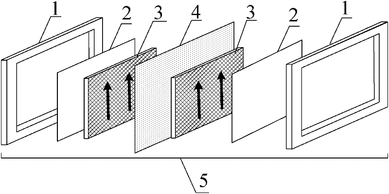
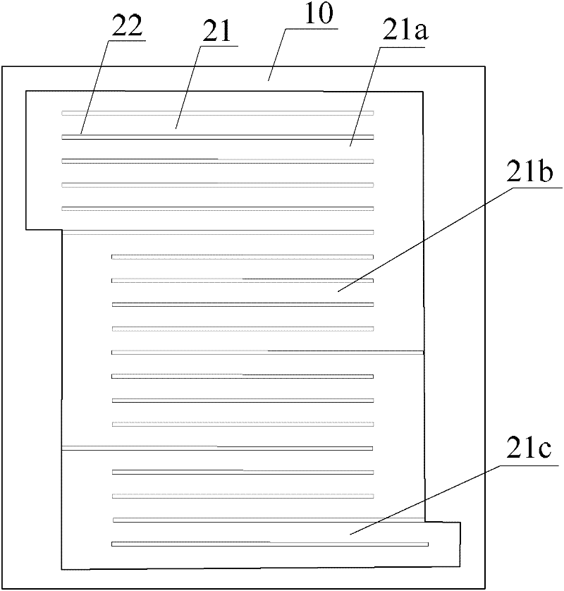
[0050] High-purity machinable graphite pole plate is used as the current collector plate material, and the flow field is engraved on it. The entire collector plate is rectangular 200mm×240mm, the thickness of the collector plate is 4mm, the depth of the runner groove is 1mm, the width of the runner groove is five times the width of the runner ridge, and the number of runners from the inlet to the outlet is six, respectively. Five, four, three and two. The charge-discharge coulombic efficiency of a single cell composed of the collector plate, the ion-exchange membrane and the graphite felt electrode is 92.5%, the voltage efficiency is 89%, and the energy efficiency is 82.3%.

example 2

[0052] High-purity machinable graphite pole plate is used as the current collector plate material, and the flow field is engraved on it. The entire collector plate is rectangular 200mm×240mm, the thickness of the collector plate is 4mm, and the channel width is five times that of the channel ridge width. Detour four times. The number of runners from the inlet to the outlet is divided into five groups, and the depths of the five groups of runners gradually decrease, which are 1.5mm, 1.3mm, 1.1mm, 0.9mm, and 0.7mm. The charge-discharge coulombic efficiency of a single cell composed of the collector plate, the ion-exchange membrane and the graphite felt electrode is 91.5%, the voltage efficiency is 87.5%, and the energy efficiency is 80.1%.

example 3

[0054] High-purity machinable graphite pole plate is used as the current collector plate material, and the flow field is engraved on it. The entire collector plate is rectangular 200mm×240mm, the thickness of the collector plate is 4mm, and the depth of the channel groove is 1mm. The flow channels of the entire flow field are divided into two groups in parallel, and a total of four detours are made from the inlet to the outlet. There are ten runners from the inlet to the outlet and they are divided into five groups. The widths of the ten runners are 25mm, 25mm, 20mm, 20mm, 15mm, 15mm, 10mm, 10mm, 5mm, and 5mm. The charge-discharge coulombic efficiency of the single cell composed of the collector plate, the ion-exchange membrane and the graphite felt electrode is 91%, the voltage efficiency is 89.5%, and the energy efficiency is 81.4%.

[0055] From the above description, it can be seen that the present invention achieves the following technical effects:

[0056] The current c...


PUM

PropertyMeasurementUnit
voltage efficiencyaaaaaaaaaa

Abstract

The present invention provides a current collecting plate of a liquid flow battery and a liquid flow battery, wherein at least one side of the current collecting plate (2) of the liquid flow battery is provided with a flow field, and the flow field includes flow channel grooves distributed at intervals ( 21) and flow channel ridges (22), the total area of ​​the cross section of each flow channel groove (21) in the flow field along the flow direction of the electrolyte decreases gradually. The present invention effectively solves the problem of energy waste and uneven flow of electrolyte caused by the lack of guiding effect of the collector plate in the prior art, and the concentration of reacting substances in the electrolyte gradually decreases with the progress of the reaction, resulting in uneven reaction rates and heat generated by the reactions at various parts of the electrodes. Uniform problems, thereby improving the charge and discharge performance and service life of the battery.

Description

technical field [0001] The invention relates to the field of batteries, in particular to a current collector plate of a flow battery and a flow battery. Background technique [0002] There are many types of flow batteries. Taking the widely used all-vanadium flow battery as an example, the all-vanadium redox flow battery is a kind of redox flow battery with long service life, high energy conversion efficiency and good safety. , environmental friendliness and other advantages, it can be used in large-scale energy storage systems for wind power generation and photovoltaic power generation, and is one of the main choices for power grid peak-shaving and valley-filling and load balancing. [0003] The all-vanadium redox flow battery uses vanadium ions V2+ / V3+ and V4+ / V5+ in different valence states as the positive and negative redox pairs of the battery, and stores the positive and negative electrolytes in two liquid storage tanks, respectively. The acid-resistant liquid pump dr...

Claims


Application Information

Patent Timeline
Patent Type & Authority Applications(China)
IPC IPC(8): H01M8/02H01M8/18H01M8/026
CPCY02E60/528Y02E60/50
Inventor 汤浩殷聪谢光有王荣贵万志伟胡蕴成
Owner 中国东方电气集团有限公司
Why Eureka
Try Eureka