Three-phase synchronous deicing device for transmission line

A three-phase synchronization, transmission line technology, applied in the installation, transportation and packaging of cables, electrical components, etc., can solve the problems of life safety, slow progress, and narrow promotion, and achieve the effect of ensuring normal work.

Active Publication Date: 2011-12-21
STATE GRID SICHUAN ELECTRIC POWER CORP ELECTRIC POWER RES INST
View PDF6 Cites 3 Cited by
  • Summary
  • Abstract
  • Description
  • Claims
  • Application Information

AI Technical Summary

Problems solved by technology

[0004] There are many deicing methods, such as the main station resonance and heating, and the second is artificial beating along the line, etc. They are either expensive, limited in promotion, or the progress is too slow, and there are even problems such as human safety.

Method used


Image

  • Three-phase synchronous deicing device for transmission line
  • Three-phase synchronous deicing device for transmission line
  • Three-phase synchronous deicing device for transmission line

Examples


Embodiment Construction

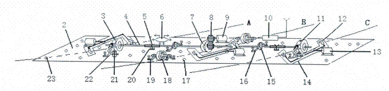
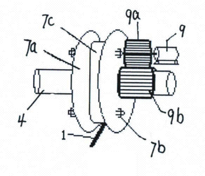
[0031] The three-phase synchronous de-icing device is composed of a robot arm and an electrical control, and the structure is as follows: figure 1 .

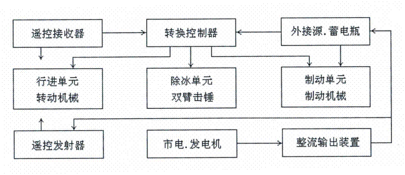
[0032] From figure 1 It can be seen in the figure: the ground can transmit various signals such as advancing, reversing, and hitting through the remote control. After receiving the remote control signal, the high-altitude cable deicing device performs sorting and conversion, and sends control signals to each unit to implement specific functions. The traveling unit is composed of a main motor, transmission gear, transmission shaft, etc.; the deicing unit is composed of a 180° rotating motor, a swing arm, and a double-click hammer; the braking unit is composed of a return spring, a brake pad and a braking motor; the working power supply can be provided by the market. Electricity or gasoline generators are provided from the ground, and storage batteries can also be provided to avoid long pull wires.

[0033] The three-phase synch...


PUM


Abstract

The invention discloses a three-phase synchronous deicing device for a power transmission line, and belongs to a device for automatically advancing and striking to deice on a three-phase power transmission line. An advancing device along the three-phase power transmission line mainly comprises three advancing wheels, a front supporting wheel and a rear supporting wheel, wherein the advancing wheels are arranged on a transmission shaft which is driven by a motor through a gear transmission mechanism; the front supporting wheel and the rear supporting wheel are positioned at a front position and a rear position of the middle part of the transmission shaft; and all the advancing wheels and the supporting wheels are arranged on a bottom plate. A striking deicing device mainly comprises an upper swing arm and a lower swing arm which are arranged on a direct current motor; and the bottom plate is correspondingly provided with a swing arm slotted hole and a crushed ice through hole for providing a movement space for the upper swing arm and the lower swing arm. A control part of the device comprises a control circuit, an emitter, a receiver and the like. The control circuit comprises a circuit for controlling the positive rotation and the reverse rotation of a traveling motor and a striking direct current motor through a plurality of relays and a coupling oscillation circuit with oscillation frequency of 2Hz consisting of the relays, an electrolytic capacitor and a triode. The device has the characteristics of remote control, automatic advancing and automatic deicing.

Description

technical field [0001] The invention relates to a deicing device for an overhead power transmission line, in particular to an electromechanical integrated device that automatically moves forward and backward on a three-phase transmission line and cable, and automatically performs mechanical vibration deicing through remote control. Background technique [0002] High-altitude cables are the lifeblood of power transmission and are related to thousands of households. However, because they are exposed, they are directly attacked by wind, frost, rain and snow, especially the impact of freezing and heavy pressure, which makes them lose their power transmission functions. In severe cases, the towers collapse and the cables Crack and break etc. [0003] For this reason, when ice cubes condense on the cables, it is very necessary to remove them urgently. [0004] There are many deicing methods, such as resonance and heating of the main station, and artificial beating along the line....

Claims


Application Information

Patent Timeline
Patent Type & Authority Applications(China)
IPC IPC(8): H02G7/16B62D57/02H02P7/20
Inventor 粟和林
Owner STATE GRID SICHUAN ELECTRIC POWER CORP ELECTRIC POWER RES INST
Why Eureka
Try Eureka